Article Text

Abstract
Purpose We used an imaging technique based on 3-dimensional (3D) C-arm CT to assess the apposition of three types of stents after coiling of intracranial aneurysms.
Methods All patients with intracranial aneurysms were considered who received stent-assisted coiling with Enterprise2, Neuroform EZ, or Neuroform Atlas stents confirmed by C-arm CT imaging at our institution between June 2015 and November 2017. A 3D digital subtraction angiography (DSA) scan for vessel imaging followed by a high-resolution cone beam CT (HR-CBCT) scan for coil and stent imaging was performed. The images were fused to obtain dual volume 3D fusion images. We investigated malapposition of the stent trunk (crescent sign) and of the stent edges (edge malapposition) and used the χ2 statistic to test for an association with stent types. Inter-rater agreement between two raters was estimated using Cohen’s kappa statistics.
Results We evaluated 75 consecutive cases. Enterprise2 stents were used in 22 cases, Neuroform EZ in 26, and Neuroform Atlas in 27 cases. By stent type, crescent sign was detected in 27% of Enterprise2, 8% of Neuroform EZ, and none of Neuroform Atlas stents (p=0.007), while edge malapposition was detected in 27% of Enterprise2, 58% of Neuroform EZ, and 30% of Neuroform Atlas stents (p=0.05). Excellent (κ=0.81) and good (κ=0.78) agreement between the raters was found for the detection of edge apposition and crescent sign, respectively.
Conclusion Stent malapposition was clearly visualized by dual volume 3D imaging. The Neuroform Atlas stents showed good apposition even in vessels with strong curvature.
- aneurysm
- angiography
- coil
- CT
- stent
This is an open access article distributed in accordance with the Creative Commons Attribution Non Commercial (CC BY-NC 4.0) license, which permits others to distribute, remix, adapt, build upon this work non-commercially, and license their derivative works on different terms, provided the original work is properly cited, appropriate credit is given, any changes made indicated, and the use is non-commercial. See: http://creativecommons.org/licenses/by-nc/4.0/.
Statistics from Altmetric.com
Introduction
Stent-assisted coiling using angiography remains the treatment of choice for wide-necked intracranial aneurysms,1 2 and stent apposition is an important factor for evaluation of the success of the treatment. It is important because incomplete stent apposition can be a potential risk factor leading to delayed ischemic events after the treatment. If malapposition is detected, antiplatelet therapy may need to be adjusted.3 In addition, stent malapposition, especially at the edges of the stent, may disturb the smooth catheterization of the microcatheter tip through the true lumen of the stent during a follow-up treatment.4
Stent apposition is usually evaluated based on a two-dimensional (2D) maximum intensity projection image acquired during the procedure by an angiographic C-arm system after the administration of a low concentration contrast medium.5–8 C-arm CT has also been applied with good results for the evaluation of stent apposition during flow diverter stent deployment before stent plasty.5 However, in these images, the precise structure of the stents and their three-dimensional (3D) spatial relation with the parent artery are difficult to evaluate.5 7 9
Progress in technology has made it possible to acquire 3D volume rendering images with C-arm systems at image qualities that can visualize stent apposition.10 However, metal artifacts generated by the metal coils still often prevent detailed imaging of the structure of the stent, particularly in patients who received stent-assisted coiling.11
Recently, an imaging method allowing stent visualization after coiling was reported in an animal study.12 High-resolution cone beam CT (HR-CBCT) images of the coil and stents were post-processed with metal artifact reduction application software in order to obtain clear images of the coils and stent. These images were fused with 3D digital subtraction angiographic (DSA) images of the parent vessels resulting in 3D fusion images that show the precise location of the stent inside the vasculature. In this study we aimed to apply this 3D fusion imaging technique to evaluate stent apposition in patients who received stent-assisted coiling of their intracranial aneurysms to investigate the proportion of stent malapposition by considering three types of stents.
Methods
Study design and sample
This study was approved by the university hospital’s ethics commission (reference # 27–236 (8121) and 29–228 (8844)). Specific informed consent for this study was waived because the data were obtained from routine examinations and treatments and analyzed retrospectively. As also requested by the IRB, we posted a notice of the conduct of the study and gave the patients the opportunity to refuse participation. All patients with intracranial aneurysms were considered who received stent-assisted coiling with the closed cell stent Enterprise2 (Johnson & Johnson, Cerenovas, USA) or one of the open cell stents Neuroform EZ or Neuroform Atlas (Stryker, Fremont, California, USA) at our institution between June 2015 and November 2017 and who underwent angiographic imaging for confirmation of the stent deployment.
3D fusion imaging
All stent-assisted coilings were performed using a biplane angiographic C-arm system (Artis Q biplane, Siemens Healthcare GmbH, Forchheim, Germany). Immediately after both stent deployment and coil placement, the patients underwent a high resolution 6 s DSA which consisted of a mask and a fill run acquisition at 70 kVp, 0.36 mGy/Fr, and 260°. For the fill run, undiluted contrast media (Ioversol 320 mg/mL, Optiray, Fuji Pharma, Tokyo, Japan) was injected at a rate of 3 mL/s for 6 s and the scan was started without delay. A 20 s HR-CBCT scan without contrast injection was then performed with parameters of 70 kVp at 1.2 μGy/Fr acquiring 496 images over 200° in a non-binned mode. The source projection frames were acquired in a 512×512 matrix covering an FOV of 22 cm diagonally. All data were reconstructed and postprocessed on a commercial workstation (syngo X Workplace, Siemens Healthcare, Forchheim, Germany). The ‘translucent’ preset was applied to the 3D-DSA images, according to our clinical routine. The HR-CBCT images were reconstructed with the addition of a streak metal artifact reduction algorithm (SMART, Siemens Healthcare) to reduce the effect of metal artifacts caused by the coil mass and stent markers.
The 3D-DSA images visualizing the vessels and the HR-CBCT images visualizing the stent and coils were fused by the workstation’s imaging fusion application (syngo DualVolume, Siemens Healthcare) to generate dual volume 3D fusion images. For the reduction of misalignment, we applied a landmark-based automatic registration that is included in the commercial application.
Classification of stent apposition
Two endovascular surgeons (NK with 15 years experience and IK with 14 years experience), blinded to each other’s results and to the patient’s clinical history, evaluated the stent apposition on the dual volume 3D fusion images using a 2-point scale (0=no malapposition, 1=malapposition). Figure 1A,B shows an example of good stent apposition. If stent malapposition was detected, the malapposition was classified according to the following criteria: (1) ‘crescent sign’, which described a gap between the trunk of the stent and the parent artery wall13 (figure 1C,D); (2) ‘edge malapposition’, which described a gap between the distal or proximal flare of the stent and the parent artery (figure 1E,F). Additionally, the observers measured the distance between the stent and the parent vessel wall of the cases with crescent sign using the electronic calipers of the workstation (figure 1G). Proportions of stent malapposition were estimated for each stent type and for each aneurysm location.
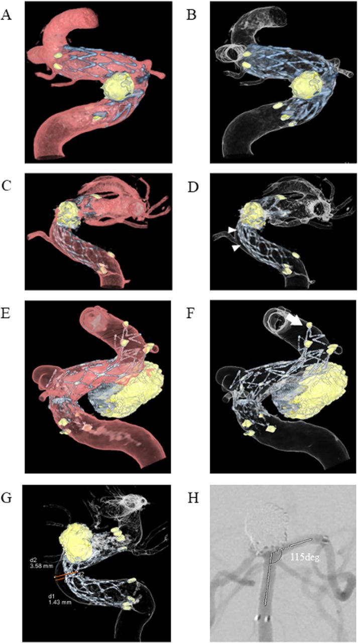
Representative images. Dual volume 3D fusion images show good stent apposition into the siphon of the left internal carotid artery (ICA) after stent-assisted coiling using Neuroform EZ for the IC-superior hypophysial artery aneurysm: (A) half lucent and (B) translucent imaging. ‘Crescent sign’ malapposition between the stent trunk of an Enterprise2 stent and the anterior wall of the ICA siphon is clearly depicted (arrow heads): (C) half lucent and (D) translucent imaging. ‘Edge malapposition’ floating distal edge of a Neuroform EZ stent is shown (arrow): (E) half lucent and (F) translucent imaging. Distance was measured using the electronic caliper of the workstation (G). The angle between the proximal and distal parent vessels was measured using the protractor function of SYNAPS work station (H).
Measurement of vessel structures
The diameters and angles of the parent vessels were measured by ruler and protractor function tools of a commercial workstation (SYNAPSE, Fuji Medical System, Japan). We used a 2D image that showed the proximal and distal neck of the aneurysm and estimated the angle between the proximal and distal parent vessels (figure 1H).
Statistical analysis
One factor analysis of variance was used for comparing age and maximal aneurysm diameter, diameter of parent vessel, angle of parent vessel, diameter and length of deployed stent of each group. The χ2 test was used to compare the proportion of women in each group, location of the aneurysm, and the occurrence of each malapposition according to stent type. The two-sample t-test was used to compare the malapposition distance according to stent type. Statistical significance was defined as p<0.05. Inter-rater agreement for detecting malapposition was estimated using Cohen’s kappa (κ) statistics. All statistical analyses were performed with Statview Version 5.0 (SAS Institute, North Carolina, USA) or Excel Version 2016 (Microsoft, USA).
Results
A total of 118 patients who fulfilled the inclusion criteria were considered. For 38 patients an imaging protocol other than high resolution 3D images and 3D-DSA imaging was used. Of the 80 patients who underwent high resolution 3D images and 3D-DSA imaging, three were excluded because of image artifacts and two were excluded because of image fusion errors. The remaining 75 patients were analyzed. Two patients had ruptured aneurysms with subarachnoid hemorrhage. Twenty-two cases were treated with Enterprise2, 26 with Neuroform EZ, and 27 with Neuroform Atlas stents. The patient characteristics are shown in table 1. There were no significant differences in age, sex, maximum diameter of aneurysm, diameter of the parent vessel, and angle of parent vessels among the three groups of patients treated with different stents, but there appeared to be a higher proportion of internal carotid artery (ICA) aneurysms stented in the Neuroform EZ and Neuroform Atlas groups than in the Enterprise2 group and a higher proportion of other vessel aneurysms stented in the Enterprise2 group than in the other groups. Significant differences were observed in diameter and length of deployed stent among the three groups.
Patient and aneurysm characteristics
Dual volume 3D fusion imaging visualized the precise structure of the stents and location in the parent vessels in all 75 cases, even for aneurysms located near the skull base. Delineation of struts was sharper for Enterprise2 and Neuroform EZ stents than for Neuroform Atlas stents. The distance between stent and vessel wall was successfully measured for all cases that showed stent malappositions of crescent sign.
Crescent sign was observed in 11% and edge malapposition was observed in 39% of all cases. There was a significant difference between the occurrence of malapposition according to stent types. Crescent sign was found in 27% of Enterprise2 and 8% of Neuroform EZ (p=0.007) but was not seen in Neuroform Atlas stents. Edge malapposition was found in 27% of Enterprise2, 58% of Neuroform EZ, and 30% of Neuroform Atlas stents (p=0.05). By aneurysm location, 14% of stents placed in the ICA showed crescent sign and 50% of stents placed in other locations showed edge malapposition. The mean distance between the stent trunk and parent vessel wall was 1.2 mm for Enterprise2 and 0.6 mm for Neuroform EZ stents. This difference was not significant, which could be due to the small sample size. Table 2 summarizes these results. No additional interventions (ie, stent plasty) were performed after detection of the malappositions. Four patients experienced postoperative complications (sensory or visual disturbance or postoperative bleeding), but these did not appear to be related to the stent malappositions. Among the four stents in these patients, one showed crescent sign and one showed edge malapposition.
Stent malapposition by stent type and location
Excellent agreement (κ=0.81) between the two observers was found for the detection of edge apposition and good agreement (κ=0.78) for the detection of crescent sign.
Illustrative cases
Case 1
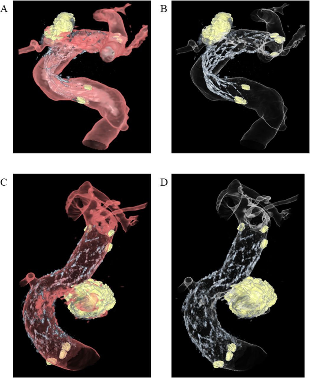
A case of an unruptured left IC-ophthalmic artery aneurysm with a maximum diameter of 4.3 mm was treated with an Enterprise stent (4.0 mm×23 mm). After stent deployment, six coils were used for aneurysm coiling. The dual volume 3D fusion images revealed a tortuous stent structure and marked malapposition of the stent trunk and flair (figure 2A,B). The postoperative course was uneventful and the patient was discharged without remarkable neurological deficit but remained under dual antiplatelet therapy and periodic follow-up by contrast enhanced MRI.

Illustrative images of stent apposition. Case 1: Translucent view of the fusion image shows marked malapposition and the tortuous structure of the stent struts of the Enterprise2: (A) half lucent and (B) translucent imaging. Case 2: All stent struts and edge markers of a Neuroform Atlas stent are seen. Although the visibility of the stent is slightly blurred, good apposition of all stent struts was confirmed: (C) half lucent and (D) translucent imaging.
Case 2
A case with an unruptured left IC-superior hypophysial artery (SHA) saccular aneurysm that showed gradual growth underwent stent-assisted coiling. The IC-SHA aneurysm had a maximal diameter of 6.7 mm and was treated with a Neuroform Atlas stent (4.5 mm×21 mm). After stent deployment, seven coils were used for coiling. The dual volume 3D fusion image visualized the detailed structure of the stent and vessel structure. The visibility of the stent was relatively blurred due to the low profile of the stent. However, excellent apposition of the stent struts onto the parent vessel was clearly seen (figure 2C,D). The patient was discharged without remarkable neurological deficit.
Discussion
Incomplete stent apposition can lead to risks of delayed ischemic events after stent-assisted coiling.3 Careful observation with antiplatelet therapy is therefore necessary if malapposition is detected.3 In our institution, patients with stent malappositions received antiplatelet therapy for longer than patients without malappositions and were followed up at shorter time intervals with MRI or DSA when the antiplatelet dose was reduced.
In this study we applied 3D fusion images for evaluating stent apposition after stent-assisted coiling. Dual volume 3D fusion images acquired by C-arm CT could be generated for all cases. Image acquisition caused no side effects for the patients. Images were ready within minutes and provided information on stent apposition to the neurosurgeons during the procedure. The metal artifact reduction software application sufficiently reduced metal artifacts from the coils in the majority of cases and the precise structure of Enterprise2, Neuroform EZ ,and Neuroform Atlas stents used in stent-assisted coiling of intracranial aneurysms could be visualized. The images could be viewed and rotated to a suitable angle by the observer for assessing stent apposition, which has been reported as a general advantage of 3D images over 2D images.14 The stent and coil images and vessel image data were acquired immediately after one another, similar to DSA imaging. Patient motion was further suppressed between the scans as the patient was under full anesthesia during the whole stent-assisted coiling procedure. When patient motion did occur between the acquisitions, it was corrected by the fusion application’s rigid registration and motion correction. This worked in all but two cases which were excluded from the analysis.
We found that images of Enterprise2 and Neuroform EZ stents showed sharper structures than those of the Neuroform Atlas stent. Neuroform Atlas is a modified open cell stent with reduced strut thickness and a number of radiopaque markers, which may be more challenging to visualize on angiography.
We observed two types of malapposition associated with stent structure and vessel curvature: crescent sign and edge malapposition. Crescent sign was more frequently observed in closed cell stents (Enterprise2) than in open cell stents (Neuroform EZ and Neuroform Atlas) whereas edge malapposition was more frequently seen in open cell stents. Furthermore, the mean distance between the stent trunk and parent vessel wall was greater for Enterprise2 than for Neuroform EZ stents, confirming that closed cell stents tend to be stiffer than open cell stents. From this study we could not conclude which malapposition is worse because of the small number of patients who experienced complications. Furthermore, we did not observe complications that were clearly related to stent malapposition.
These factors should be recognized for patients treated by stent-assisted coiling,13 as both types of incomplete malapposition can interfere with the maneuverability of the guidewires or microcatheters through the stents.4 Our study could thus confirm the estimated proportions of stent malapposition detected by 3T MRA imaging.1
For closed cell stents, malapposition was more frequently found at the carotid siphon. The sharp angle of the vessel combined with the relative stiffness of the closed cell stent may predispose this location to the occurrence of this type of malapposition. In contrast, the Neuroform Atlas stent is a modified open cell stent that has recently been introduced for endovascular treatment of wide-necked aneurysms and is compatible with current microcatheters that have internal diameters of 0.0165 inch. This design improves delivery in small and/or tortuous vessels. The stent strut comprises zigzag shapes that are joined by interconnections. There are four interconnections evenly spaced throughout the strut. Each alternating strut is made up of 8 or 12 crowns, with the most proximal row of cells being a closed cell of 12 crowns.2 15 This new design may be the reason for more accurate stent apposition in the carotid siphon. These results suggest that the low-profile open cell stents tend to fit adequately onto the vessel wall compared with other stents.
Studies on stent visibility or stent malapposition have been previously reported using different imaging techniques. Postoperative MRI with gadolinium injection can be an option to evaluate the stent structure and vessels surrounding the aneurysm.16 Intraoperative optical coherence tomography has also emerged as a modality to evaluate stent apposition and thrombus organization.17 However, this technique requires a special catheter insertion into the vessels in question. C-arm CT acquisition with a low contrast medium has become a common visualization technique for stents,7 as well as for intraprocedural evaluation of stent apposition during flow diverter stent deployment before stent plasty.5 However, these methods provide only 2D slice images.5 7 9 In treatment with flow diverter stents, the assessment of stent apposition and its correction are indispensable to prevent delayed ischemic complications.8 9 Dual volume 3D fusion images would allow the observer to select the best examination angle to detect stent appositions.14 Furthermore, images are easy to acquire with state-of-the-art C-arm systems. Dual volume 3D fusion imaging may be a promising tool for investigating apposition of flow diverters as well.
Limitations of study
Our study has several limitations. Only a small number of cases from a single center were included. Not all patients who underwent stent-assisted embolization could be analyzed since the imaging protocol for stent apposition confirmation is not standardized in our institution. This may have introduced selection bias. Additionally, we investigated stent apposition for only three types of stents and did not assess stent apposition of flow diverters. Some error may have been introduced in the measurements of distance between the stent and vessel wall in the crescent sign due to manual windowing of the images. Similarly, the reconstruction parameters were not standardized and could potentially affect the visibility of the stent structures and vessels.18 Diameters and lengths of the deployed stents were not the same for each stent type due to their commercial availability. Finally, the radiation dose to the patients has not been investigated.
Conclusion
Dual volume 3D fusion images obtained from 3D-DSA and HR-CBCT allowed detailed delineation of stents within the vasculature. Different types of stent malapposition according to closed or open cell structure of the stent were clearly observed. The open cell Neuroform Atlas stent showed better apposition than the other types of stents.
References
Footnotes
Contributors Conception and design: IY and YM. Data acquisition: NK, IY, TI, IK, KN, TK, SK, YA and YM. Analysis: NK, IK, YA and KO. Drafting the manuscript: NK, KO and YM. Critically revising the article: All authors. Final approval of the version to be published: All authors. Agreement to be accountable for all aspects of the work in ensuring that questions related to the accuracy or integrity of any part of the work are appropriately investigated and resolved: All authors.
Funding This work was supported by Siemens Healthcare K.K. grant number C00221025.
Competing interests KO is an employee of Siemens Healthcare.
Provenance and peer review Not commissioned; externally peer reviewed.
Data sharing statement There are no additional unpublished data available.
Patient consent for publication Not required.