Article Text

Abstract
Background Although flow diversion is a promising procedure for the treatment of aneurysms, complications have been reported and it remains poorly understood. The occurrence of adverse outcomes is known to depend on both the mechanical properties and flow reduction effects of the flow diverter stent.
Objective To clarify the possibility of designing a flow diverter stent considering both hemodynamic performance and mechanical properties.
Materials and methods Computational fluid dynamics (CFD) simulations were conducted based on an ideal aneurysm model with flow diverters. Structural analyses of two flow diverter models exhibiting similar flow reduction effects were performed, and the radial stiffness and longitudinal flexibility were compared.
Results In CFD simulations, two stents–Pore2-d35 (26.77° weave angle when fully expanded, 35 μm wire thickness) and Pore3-d50 (36.65°, 50 μm respectively)–demonstrated similar flow reduction rates (68.5% spatial-averaged velocity reduction rate, 85.0% area-averaged wall shear stress reduction rate for Pore2-d35, and 68.6%, 85.4%, respectively, for Pore3-d50). However, Pore3-d50 exhibited greater radial stiffness than Pore2-d35 (40.0 vs 21.0 mN/m at a 3.5 mm outer diameter) and less longitudinal flexibility (0.903 vs 0.104 N·mm bending moments at 90°). These measurements indicate that changing the wire thickness and weave angle allows adjustment of the mechanical properties while maintaining the same degree of flow reduction effects.
Conclusions The combination of CFD and structural analysis can provide promising solutions for an optimized stent. Stents exhibiting different mechanical properties but the same flow reduction effects could be designed by varying both the weave angle and wire thickness.
- Aneurysm
- Blood Flow
- Device
- Flow Diverter
- Stent
This is an Open Access article distributed in accordance with the Creative Commons Attribution Non Commercial (CC BY-NC 4.0) license, which permits others to distribute, remix, adapt, build upon this work non-commercially, and license their derivative works on different terms, provided the original work is properly cited and the use is non-commercial. See: http://creativecommons.org/licenses/by-nc/4.0/
Statistics from Altmetric.com
Introduction
Flow diversion is a promising procedure for the treatment of intracranial aneurysms (IAs), especially those that are difficult to treat using coils. Flow diversion works by employing a stent to divert blood flow away from the IA, thus promoting thrombosis within its cavity. As a secondary effect, endothelial and neointimal tissue will grow across the IA neck, with the diverter functioning as a scaffold.1 However, the safety and efficacy of this procedure are incompletely understood, and complications have been reported, such as incomplete formation2 and non-formation3 of clot inside the aneurysm. Furthermore, aneurysm rupture after treatment1 ,2 can occur following the use of such a device. Standard flow diverters that may be purchased from commercial sources are constructed of braided, helical metal wires, and the diverting power of these devices is determined partly by their porosity and pore density.1 ,4 The porosity of a diverter is calculated as the percentage of the overall stent area that is open and metal-free, while the quantity of pores per unit area (typically one square millimeter) represents the pore density.5 Prior studies have found that both increasing the pore density and reducing the porosity can increase the extent to which the velocity in the IA is decreased.6 In addition, lower porosity values make the growth of endothelial and neointimal tissues easier,1 although thrombosis of branches originating from the stented segment can result from overly low porosity or significantly increased pore density.7
The differences in stent characteristics such as wire thickness and weave angle can lead to different flow reduction effects, and also different mechanical properties. Complications such as extra-aneurysmal thrombosis and emboli detachment can result from the use of inadequate radial forces while applying the stent, and artery wall damage can be caused by applying an excess of such forces.8 In addition, since the diverter must navigate convoluted arterial pathways, flexibility in the longitudinal direction is also important.8 For these reasons, optimization or design of flow diverters must consider both flow reduction effects and mechanical properties. However, investigations of typical helical braided flow diverter stents focusing on their mechanical properties have not yet been performed. Further, any previous investigations focusing on both flow reduction effects and the mechanical properties of typical stents have never been reported.
In this study, to show the possibility of designing a flow diverter stent by considering both flow reduction effects and mechanical properties, computational fluid dynamics (CFD) simulations were first performed for an idealized aneurysm model with and without a helical braided flow diverter stent among 11 different stents. Then, two different stents exhibiting similar flow reduction effects were selected, and structural analysis was performed on them. The radial stiffness and longitudinal flexibility values of these two devices were computed.
Material and methods
CFD analysis
CFD analysis was performed on a virtual aneurysm model both with and without a flow diverter in place.
Virtual aneurysm geometry
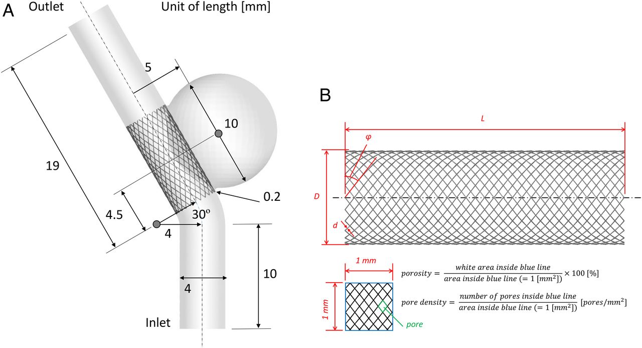
An idealized sidewall-type saccular aneurysm geometric model was created,6 as shown in figure 1A. An internal carotid artery aneurysm was assumed, since this is the most common site for treatment with flow diverters, and the parent artery was given a width of 4 mm. The IA was modeled using a sphere-shaped dome with a radius of 5 mm. Although cerebral arteries are actually curved, the parent artery was represented by a straight tube for the region in which the flow diverter was deployed to simplify and clarify the comparison; therefore, the stent had no bending deformation. This simplest possible model, incorporating a spherical IA with a straight parent artery, has often been adopted for simulations using virtual IAs.6 ,9 ,10 However, this model generates unrealistic flow in the IA, so a bend was incorporated at a region more proximal than the site at which the flow diverter was deployed so as to obtain sufficient inflow to the IA.

Definitions of the configurations. (A) Illustration of the ideal aneurysm model used for computational fluid dynamics simulations. (B) Definitions of structural parameters of helical braided stents (D, diameter of stent; d, wire thickness; φ, weave angle; L, length of stent).
Definition of the flow diverters
Figure 1B shows the definition of variables for the specifications of the stent, and table 1 gives details of the compared stents. To determine the stent specifications, a reference stent (Pore1-d30) based on the Pipeline Embolization Device (PED; Covidien, Irvine, California, USA), was created as described in a previous study.4 Each stent was composed of 48 wires;11 these wires were braided in the same patterns as those in previous studies.12 Although the PED is composed of two different wire thicknesses in a 3:1 ratio,4 in our study, the stents contained only a single wire thickness and a single type of material to simplify the comparison and to help clarify the relationship between the specifications and the resulting flow reduction effects and mechanical properties. Four different stents were subsequently designed with the same porosity values by increasing the wire thickness, d, in 5 μm increments and the weave angle, φ, to generate Pore2-d35, Pore3-d40, Pore4-d45 and Pore5-d50. Finally, in the case of Pore1-d30, Pore3-d40 and Pore5-d50, two additional stents were designed having the same pore density but with different porosity values by changing the wire thickness (30, 40 or 50 μm) and adjusting the weave angle slightly, to generate Pore1-d40, Pore1-d50, Pore3-d30, Pore3-d50, Pore5-d30 and Pore5-d40.
Details of the compared stents on computational fluid dynamics (CFD) simulations
Mesh generation methods
Unstructured volume grids were generated using the ICEM CFD V.16.0 software package (ANSYS, Inc, Canonsburg, Pennsylvania, USA) and employing tetrahedral elements with a maximum size of 0.3 mm together with prism grids. The prism grids were fitted to the vessel wall except for the part where the stent was deployed, with the first layer having a thickness of 0.02 mm, and the remaining seven layers having a total thickness of 0.3 mm. In cases involving a flow diverter stent, 0.008 mm elements were created around the stent.13 The total number of elements in the meshes ranged from approximately 1.0 million for the computation without the stent, and 28.0–60.0 million for computation with the stent. Those grid resolutions were fine enough to obtain results that were independent of the grids.
Computational conditions
Continuity and Navier–Stokes equations for incompressible flows were solved using ANSYS CFX V.16.0 (ANSYS, Inc). This solver has been used in studies of IAs14–16 and the accuracy for the computation of velocity fields has been previously validated.17 A steady flow analysis was performed while imposing a Poiseuille velocity profile with a maximum velocity of 1 m/s at the inlet boundary and fixing the pressure at 0 Pa at the outflow boundary. It has been reported that steady state represents the pulsatile solution and only causes a change in magnitude of flow parameters such as velocity. In particular, the steady-state analysis is sufficient to compare the effects of stents.18 Rigid and no-slip boundary conditions were assumed on all the vascular walls. The blood density and viscosity were assumed to be 1100 kg/m3 and 0.0036 Pa·s, respectively. The flow was assumed to be laminar since the Reynolds number based on the diameter of the parent artery (4.0 mm) and average velocity (0.5 m/s) was about 611. To allow the flow to develop before reaching the outlet boundary, the outlet was extended by connecting a 75 mm straight pipe.
Comparison parameters
Flow reduction rates were computed for the spatial-averaged and maximum velocity within the IA and the area-averaged and maximum wall shear stress (WSS) at the IA surface. The reduction rate of each variable, X, was defined as in the following equation.13 1Xuntreated and Xtreated indicate the variable computed in CFD without and with the stent, respectively. Please note that the IA model in CFD with and without the stent have the same shape.
Structural analysis
As will be noted in the ‘Results’ section, two different stents (Pore2-d35 and Pore3-d50) generating the same flow reduction effects were identified. To investigate the differences in the mechanical properties between these two stents, structural analysis of each stent was performed. The longitudinal flexibility and the radial stiffness of each device were assessed via simulated bending and crimping tests. Because of problems related to the instability of these simulations resulting from non-linear deformation and contact properties, these computations were performed using the ABAQUS/explicit (SIMULIA, Providence, Rhode Island, USA) finite element analysis algorithm. The solver's general contact algorithm was employed to model contacts, with the intrawire contacts being assigned a friction coefficient of 0.15.19 During these simulations, the geometry of the stent was represented by a beam-element mesh having a circular shape. The nominal element size was set as 0.08 mm for Pore2-d35 and 0.09 mm for Pore3-d50, which corresponded to one-quarter of the length from one wire crossing point to the next wire crossing point along a wire. These element sizes were chosen by performing the grid independence test and confirming that the computation outcomes were not affected by the grid.12 Table 2 summarizes the properties of the cobalt–chromium–nickel (Co–Cr–Ni) wires that were used to model the wires.12
Material properties assigned to simulated cobalt–chromium–nickel (Co–Cr–Ni) wires
Crimping tests
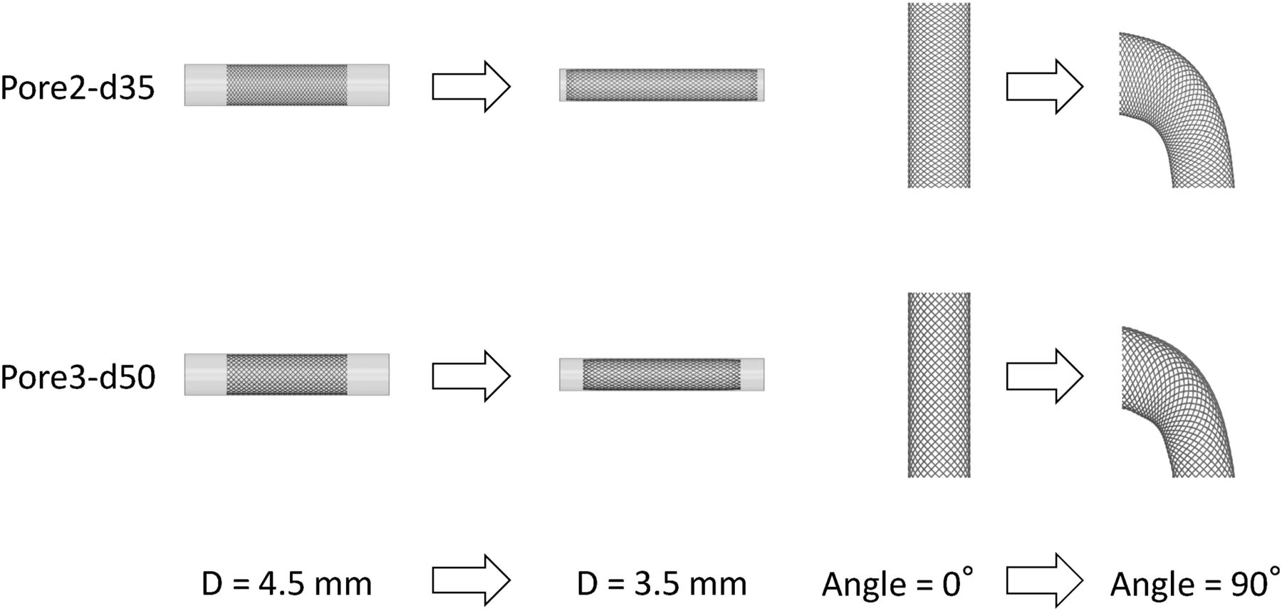
The cylindrical crimper employed during crimping trials had a wall thickness of 0.05 mm, an axial length of 17 mm, an outer diameter of 4.6 mm and an inner diameter of 4.5 mm. This section was given the same mechanical properties as steel (density=7.9 g/cm3, elasticity=202 GPa, Poisson's ratio=0.3) to simplify the simulation process.12 An inward radial displacement of 0.5 mm was uniformly applied to this section, as shown in figure 2A. The crimper geometry was modeled using a shell element mesh with a mesh size of 0.09 mm. Once again, the grid had no effect on the simulation outcome. The stents in these simulations had lengths equal to 10 mm and each crimper was longer than the associated stent. The contact region between the wire and the crimper was given a friction coefficient of 0.01.12 The normal contact forces acting on nodes along the interior walls were summed and described as ‘Fr’, and then divided by the stent length ‘L’ to determine the ratio of the force orthogonal to the inner crimper surface to unit stent length (Fr/L). Both Fr/L and Fr were compared. Each simulation was conducted over a time of 0.2 s. This analysis interval was chosen to ensure that the overall kinetic energy of the system was well below the potential strain energy so as to obtain the desired static behavior.20 The total number of elements was 42 825 for Pore2-d35 and 38 649 for Pore3-d50.

Configurations of structural analysis. (A) Configurations before and after crimping (left): before crimping (t=0 s), crimper inner diameter D=4.5 mm; after crimping (t=0.2 s), D=3.5 mm. (B) Configurations before and after bending (right): before bending (t=0 s), bending angle θ=0°; after bending (t=0.54 s), θ=90°.
Bending tests
These trials involved the bending of 10 mm long stents, as shown in figure 2B, by rotating one end through an angle θ (ranging from 0 to 90°) while holding the opposite end steady. All the top end nodes were coupled with all degrees of freedom, and all the bottom end nodes were fixed. The rotation center was located at the center of the stent. For the same reasons presented above in the summary of the crimping trials, an analysis time of 0.54 s was selected. The total number of elements was 13 152 for Pore2-d35 and 8976 for Pore3-d50.
Results
CFD analysis
Relationships between the stent specifications and flow reduction effects
Figure 3A shows the velocity distributions along the cross-section (representing a plane of symmetry) across the center of the IA and the parent artery. Please note that the maximum value of the figure legend for the case without the stent is 10 times larger (1.0 m/s) because the velocity in the IA was much higher. Tables 3 and 4 summarize the reduction rates of the average and maximum of velocity and WSS. When the reduction rates of the hemodynamic variables were compared between the stents having a similar weave angle (for instance, between the stents named ‘Pore1-’), the reduction rates of average velocity, maximum velocity and average WSS increased as the wire thickness was increased. In contrast, the stents having the same wire thickness (for instance, the stents named ‘-d30’) produced greater reduction rates for those variables as the weave angle was decreased. For porosity and pore density, when comparing stents having the same porosity, not all the reduction rates were equal or similar—that is, the flow reduction effects did not depend only on porosity, but also on pore density. As the porosity decreased and the pore density increased, the reduction rates of the hemodynamic variables increased. These results are in good agreement with data reported from previous research, as discussed in the ‘Introduction’. Similar reduction rates and velocity distributions were observed when modeling Pore2-d35 (reduction rate of average velocity 68.5% and reduction rate of average WSS 85.0%) and Pore3-d50 (reduction rate of average velocity 68.6% and reduction rate of average WSS 85.4%) as shown in figure 3A.
Reduction in velocity
Reduction in wall shear stress (WSS)
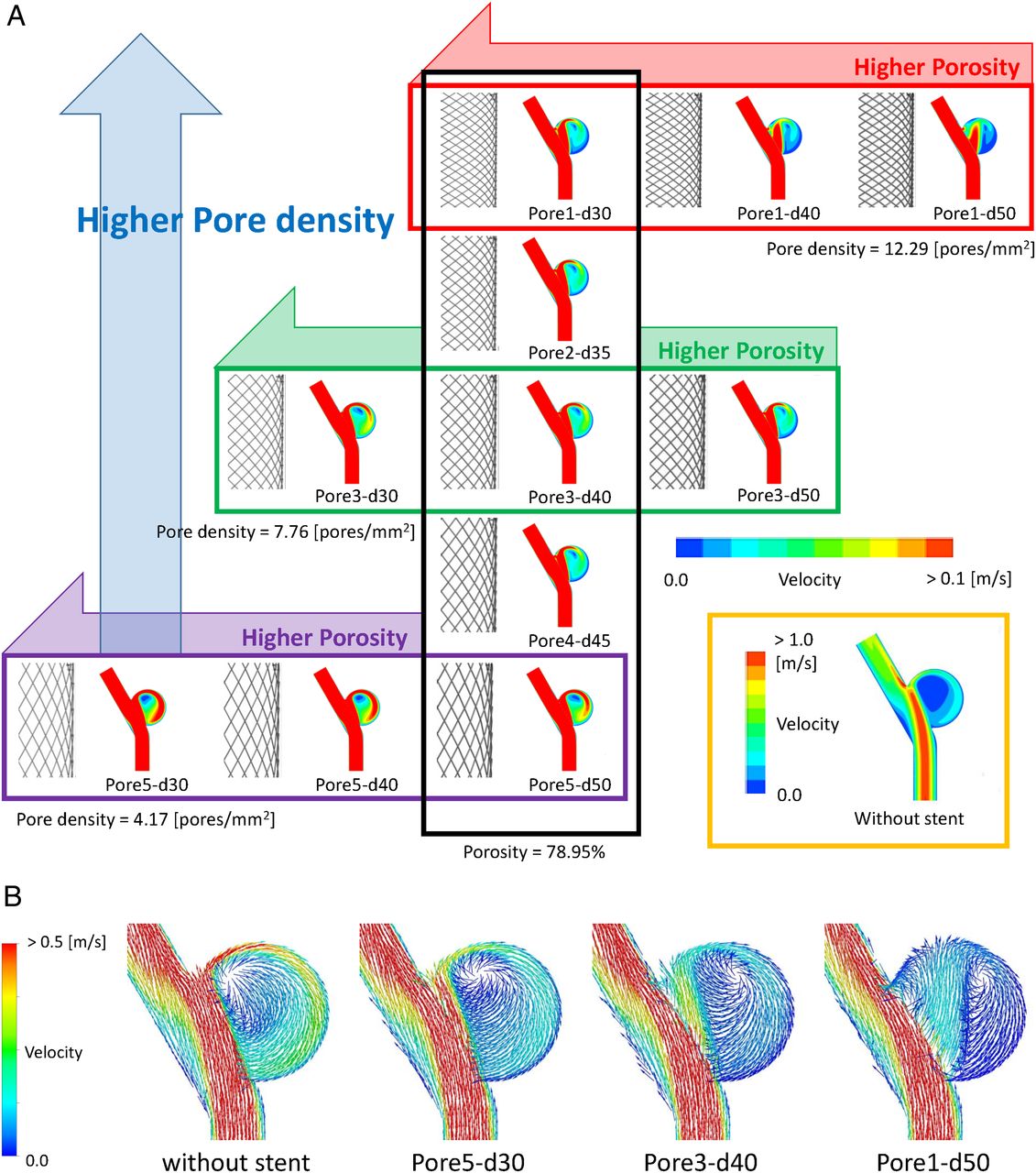
Visualizations of computational fluid dynamics analysis. (A) Velocity distributions at a cross-section (plane of symmetry) across the center of the intracranial aneurysm and the parent artery. (B) Velocity vector fields at the cross-section.
Change of flow pattern by the deployed stent
Figure 3B shows the velocity vector fields on the same cross-section as the velocity distributions for the case without the stent and with the stent showing minimum, medium and maximum velocity reduction rate (Pore5-d30, Pore3-d40 and Pore1-d50, respectively). In the case without the stent, part of the flow colliding with the distal neck region entered into the IA in accordance with the inertia. The flow entering the IA swirled around the IA in a clockwise direction (see figure 3B without stent). This flow pattern is induced in typical side-wall IAs.6 ,9 ,10 In the cases with the stent, the flow entering the IA was reduced remarkably as shown in the previous section (see table 2). The flow through the stent separated into the main flow swirling around the IA and less flow leaving the IA from the distal neck region directly. Those two parts of the flow included the flow colliding with the IA wall. As the stent had high flow reduction effects (low porosity and/or high pore density), the position of the collision area moved apart from the neck to the dome.
Structural analysis
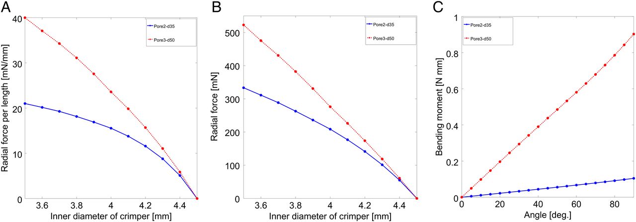
Crimping and bending tests were applied to Pore2-d35 and Pore3-d50, both of which exhibited similar flow reduction effects (see figure 4). The resistance to crimping and bending in both of the stents increased monotonically to radial compression or the bending angle. Pore3-d50, which had a larger weave angle and wire thickness, was found to be more resistant to crimping and bending. Therefore, it possessed greater radial stiffness and less longitudinal flexibility. Clinically, Pore3-d50 was more likely to have resistance to fitting into a curved vessel and remain in the implanted position with larger radial force. These results suggest that mechanical properties can be adjusted while maintaining the same hemodynamic reduction effect. For the change in length, 10 mm of Pore2-d35 and Pore3-d50 were changed to 15.9 and 13.1 mm, respectively, when crimped to a diameter of 3.5 mm in the crimping tests. Therefore, Pore2-d35 is more likely to change in length when its diameter is changed.

Comparison results of structural analysis. (A) Results of crimping tests (radial force per length; Fr/L). (B) Results of crimping tests (radial force; Fr). (C) Results of bending tests (bending moment).
Discussion
Deploying a flow diverter stent diverts blood flow away from the aneurysmal sac, while also promoting thrombosis formation and thus preventing the IA from rupturing. For the flow reduction effects, such as the reduction rate of average velocity in the IA, both pore density and porosity are important factors. This study showed that as porosity decreased or pore density increased, the flow reduction effects increased. These trends have also been identified in prior studies, as described in the ‘Introduction’. Thus, a stent having a smaller weave angle and a larger wire thickness will generate a greater flow reduction effect.
Depending on the stent, the flow pattern in the IA changed. In this study, as the stent exerted high flow reduction effects, the position of the collision area moved apart from the neck to the dome. Although the energy of the flow colliding on the IA wall is weakened by the stent, the transition of the collision spot to the weak position may result in rupture of the IA. As a thin-walled region may be predicted by CFD simulation,21 the risk described above may also be predicted by CFD.
Previous research has also produced other findings for flow diverters. Ma et al22 and Xiang et al23 investigated the possibility of manipulating the local porosity at the aneurysm orifice, and reported that this affected the flow reduction. Janiga et al24 showed that variations in blood flow reduction were obtained when changing the local stent compression below the ostium. Anzai et al25 reported that denser wires situated in the inflow area lead to more effective flow reduction, while Kim et al26 showed that porosity and wire shape both affect the flow reduction.
However, if a stent is designed that effectively leads to flow reduction but that stent is difficult to deploy or produces a high risk of complications such as migration, it would not be suitable for clinical use. Complications after treatment depend on the mechanical properties of the device. The implantation of stents is known to affect the blood vessel curvature.27 Mori et al28 ,29 demonstrated that expansion of the parent artery after stent implantation reduces flow. These changes in the parent artery depend on the mechanical properties of the stent; therefore, these mechanical properties should be considered as well as flow reduction effects during the design of an optimized stent.
In this study, two stents with similar flow reduction effects were simulated by structural analysis, and two mechanical properties (radial stiffness and longitudinal flexibility) were compared between the two stents as a preliminary study. No previously published studies have assessed both flow reduction effects and mechanical properties. Our study showed that the two stents compared had different mechanical properties. This result indicated that changing the wire thickness and weave angle allows adjustment of the mechanical properties while maintaining the same degree of flow reduction. When designing a helical braided stent intended to create suitable flow reduction effects, the mechanical properties of the device can be varied while obtaining similar flow reduction effects by either (i) decreasing or (ii) increasing the weave angle and wire thickness. In the former case, the longitudinal flexibility will be increased. Generally, the radial stiffness increases as the weave angle decreases or as the wire thickness increases. In this study the stent having a larger weave angle and wire thickness (Pore3-d50) indicated higher radial stiffness. Therefore increasing the weave angle and wire thickness may lead to an increase in radial stiffness. In this way, it is possible that patient-specific optimized stents could be designed by considering the required optimal mechanical properties and hemodynamic performance. To realize such a tailor-made stent design, the combination of CFD and structural analysis provides a promising solution.
Finally, foreshortening is a serious problem related to stent deployment as it can cause misplacement.30 In our study, the stent having smaller weave angle (Pore2-d35) changed its length to a greater degree when crimped. For helical stents, the degree of the foreshortening depends on the weave angle. The degree of foreshortening decreases as the weave angle increases. This characteristic should also be considered in the design of optimal stents.
Limitations
In this study, CFD simulations were performed using a virtual IA model, and structural analyses were conducted for the two stents found to have similar flow reduction effects. To carry out a simple comparison in CFD, the parent artery was modeled by a straight tube in the region in which the flow diverter was employed, and the stent had no bending deformation. However, if the two stents considered herein were to be deployed in a curved pipe or vessel, they might be expected to perform differently from each other. Additionally, various stents that theoretically should generate the same flow reduction effects may perform differently in different patients, so further studies using patient-specific geometries are needed. In addition, the number of wires and the wire materials were held constant in this study. In future work, these factors should also be considered as design variables, in addition to wire thickness and weave angle. For the structural analysis, no validation against experimental data was performed. However, the solver used in the presented work (ABAQUS/explicit) has been validated for the structural analysis of various stents in previous studies,12 ,20 based on which the computational conditions such as friction coefficients, materials and element models were defined in this study. Therefore, it is assumed that the present simulations are valid. Finally, in order to design an optimized stent for individual patients, it is necessary to reach a consensus on establishing criteria for flow reduction and mechanical stent properties.
Conclusions
To design a stent that is tailor-made, both flow reduction effects and mechanical properties should be considered. This study demonstrated the possibility of designing a typical helical braided flow diverter stent that optimizes both flow reduction effects and mechanical properties. The combination of CFD and structural analysis may be a promising solution applied to patient-specific IAs.
Supplemental material
References
Footnotes
Contributors All authors helped to design the study. TS, HT and SF performed the simulations and collected and analyzed the data. CD, TI, HM, NF, YM and MY helped to evaluate the data. TS and HT wrote the manuscript.
Funding This work was supported by Siemens Healthcare K.K. grant number 35993-00211563. NTT Docomo, Inc, Stryker Japan K.K. and Asahi Intecc Co, Ltd.
Competing interests None declared.
Provenance and peer review Not commissioned; externally peer reviewed.
Data sharing statement The authors are willing to share spreadsheets from their data acquisition and experimental set-up details on request.