Article Text

Abstract
Purpose The purpose of this study was to investigate hemodynamics and coil distribution with changing coil stiffness and length using the finite element method (FEM) and computational fluid dynamics (CFD) analysis.
Methods Basic side-wall and bifurcation type aneurysm models were used. Six types of coil models were generated by changing the coil stiffness and length, based on commercially available embolic coils. Coil embolization was simulated using FEM. CFD was performed to characterize the hemodynamics in the aneurysms after embolization. Coil distribution and velocity reduction in the aneurysms were evaluated.
Results The median value of radial coil distribution was shifted from the center to the outer side of the aneurysmal dome by changing coil stiffness: harder coils entered the outer side of the aneurysmal dome more easily. Short coils were more distributed at the neck region, since their small size made it easy for them to enter the tighter area. CFD results also indicated that velocity in the aneurysm was effectively reduced when the coils were more distributed at the neck region and the outer side of the aneurysmal dome because of the disturbance in blood inflow.
Conclusions It is easier for coils to enter the outer side of the aneurysmal sphere when they are harder. If coils are short, they can enter tighter areas more easily. In addition, high coil density at the outer side of the aneurysmal dome and at the neck region is important to achieve effective velocity reduction.
- aneurysm
- blood flow
- coil
This is an open access article distributed in accordance with the Creative Commons Attribution Non Commercial (CC BY-NC 4.0) license, which permits others to distribute, remix, adapt, build upon this work non-commercially, and license their derivative works on different terms, provided the original work is properly cited and the use is non-commercial. See: http://creativecommons.org/licenses/by-nc/4.0/
Statistics from Altmetric.com
Introduction
Endovascular coil embolization is a standard procedure for treating intracranial cerebral aneurysms,1 which is preferred to craniotomy for neck clipping because of its minimal invasiveness and low failure rate.2–5 However, its limitation is recanalization few months or years after embolization.6–11
With the great advances in simulation techniques using computational fluid dynamics (CFD), some researchers have attempted to characterize the hemodynamics after coil embolization.12–14 Simulation of coil embolization has also been developed using the combination of finite element method (FEM)-based structural analysis and CFD analysis.15 Although these studies have provided important pointers to understanding the flow mechanisms in embolized aneurysms, there have been no reports on the effects of changing coil characteristics such as stiffness or length, which may also have an impact on coil distribution inside aneurysms, causing hemodynamic changes.16 In addition, in all previous studies the coils were not exactly modeled based on actual products. To prevent aneurysmal recanalization, surgeons need to understand better the basic characteristics of coils and the effects of changes in coil stiffness and length during the operation (eg, where harder and shorter coils are more easily deployed). It is also important to know the hemodynamic effects of coil distribution in aneurysms.
Thus, the aim of this study was to investigate the hemodynamics and coil distribution associated with changing coil stiffness and length using FEM and CFD analyses. Coils were modeled based on actual commercially available embolization coils. FEM was used to simulate coil embolization and to obtain the geometry of embolizing coils. Hemodynamics within the aneurysms were characterized using CFD to investigate flow changes after embolization. Velocity reduction and coil distribution in the aneurysms were then evaluated.
Materials and methods
Basic aneurysmal model
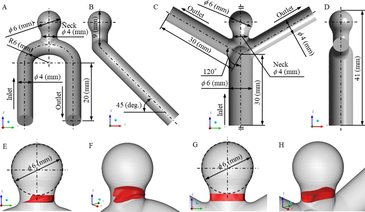
Two types of basic aneurysmal models imitating an internal carotid artery aneurysm and a middle cerebral artery aneurysm were generated to model a side-wall and a bifurcation type aneurysm, respectively. These models are shown in figure 1A, C from the yz plane and figure 1B, D from the xz plane. Both geometries at the aneurysm were the same, with a dome diameter of 6 mm and a neck diameter of 4 mm. The details are included in the online supplementary data.
Supplementary file 1

Detailed geometries of the generated basic aneurysm models and the definition of the inflow neck volume region (red area). (A, B) Side-wall type aneurysm from the yz plane and the xz plane. (C, D) Bifurcation type aneurysm from the yz plane and the xz plane. (E, F) Inflow neck volume region in a side-wall type aneurysm from the yz plane and bird’s eye view. (G, H) Inflow neck volume region in a bifurcation type aneurysm from the yz plane and bird’s eye view.
Coil models (Stryker Target 360 series)
Various coil models were generated based on commercially available embolic coils, the Stryker Target 360 series (Stryker Neurovascular, Fremont, California, USA). Considering the actual coil geometries, initial shape, and material properties, four types of models were generated based on real products (Target 360 Standard (hard), Target 360 Soft (medium hard), Target XL 360 Standard (medium soft), and Target XL Soft (soft)), and two types of length-changed custom models (medium and short) were generated based on Target XL 360 Soft (long), as shown in online supplementary table S1 and online supplementary figure S1. Only the coil lengths were changed in the two custom models we used (ie, the design variables were the same as Target XL 360 Soft except for the length). The properties of the coils shown in parentheses were assessments by the authors to demonstrate coil differences. The coil size was 6 mm, which is the same as the aneurysmal diameter, and the total length of the inserted coils was 200 mm in all models. While the total coil length remained the same, the number of inserted coils varied to investigate the effect of a single coil length.
Supplementary file 2
Simulation of coil embolization by FEM
FEM-based structural analysis software Abaqus/Explicit ver. 6.14 (Dassault Systèmes Simulia Corporation, Providence, Rhode Island, USA) was used to simulate coil embolization. The cross-sectional plane of the coil was assumed to be a cylindrical plane; the outside diameter and wall thickness corresponded to the primary coil diameter and primary wire diameter, respectively. These simplifications are reasonable because the primary coil was constructed with a tightly wound primary wire in the actual coil. The equivalent Young’s modulus (Ecoil) and the equivalent shear modulus (Gcoil) of the coils were defined considering the geometry of the primary coil and the material composition of 92% platinum and 8% tungsten alloy, which was used in the Target series.17 18
Simulation of coil embolization was started by filling the coil into the catheter, considering the effect of the coil’s shape memory when it was released from the catheter. The tip of the straight catheter was placed at the center of the aneurysm and its angle was vertical to the neck plane. The boundary condition for coil movement was imposed to the tip of the coil under stress-free conditions at a speed of 10 mm/s. Once the catheter was filled with the coil and the tip of the coil reached the distal orifice of the catheter, the coil was deployed into the aneurysm at a speed of 5 mm/s.19 After generateing the virtual aneurysmal neck as a rigid surface, we ascertained that the deployment of the coil was inside the aneurysm. This method is a reasonable simulation of balloon-assisted techniques. The aneurysm, neck surface, and catheter were assumed to be rigid and completely fixed during the simulation. Full details of the FEM analysis are given in the online supplementary data.
Hemodynamic analysis by CFD
A computational unstructured grid was generated using ANSYS ICEM CFD 15.0 (ANSYS, Canonsburg, Pennsylvania, USA) based on the geometry data of the basic aneurysm models and the embolizing coil obtained from the FEM analysis. The blood flow was analyzed using ANSYS CFX 15.0 (ANSYS). The inlet boundary condition was 0.003465 kg/s, which is the diastolic value in healthy adults.20 At the outlet the static pressure was fixed to 0 Pa. Details of the CFD analysis are given in the online supplementary data.
Evaluation methods
Various parameters were defined to evaluate the embolized aneurysm, coil distribution in the aneurysm, and hemodynamic changes.
The classical parameter, the volume embolization ratio (VER), was defined as the ratio of physically inserted coil volume to aneurysm volume as follows:

VER is also well-known as packing density (PD) to determine the status of embolizing coils in actual clinical settings.21
An original parameter, the neck volume embolization ratio (NVER), was defined by the following equation:

where the inflow neck volume is the volume of the region with >0 blood velocity in the Z direction (ie, w >0) in the neck and the coil volume in the neck is the coil volume located in the inflow neck volume region. The neck region was defined as the space between the neck surface and the bottom of the aneurysmal sphere (figure 1). Although VER and NVER are the same in terms of physical coil volume, VER shows the whole state of the embolized aneurysm and NVER focuses on the inflow neck region.
In addition, the radial distance (RD) was calculated in each node of the coil to evaluate the radial coil distribution in the aneurysm. This is formulated as:

where x RD, y RD, and z RD are the coordinates of the node point of the embolizing coil.
The velocity reduction rate (VRR) was defined to identify the flow change between before and after embolization:

where the velocity in aneurysmbefore is the averaged velocity in the aneurysm before embolization (uncoiled aneurysm) and the velocity in aneurysmafter is the averaged velocity in the aneurysm after embolization.
The wall shear stress reduction rate (WSSRR) was defined as follows:

where the averaged WSS in aneurysmbeforeand the averaged WSS in aneurysmafter is the spatial-averaged WSS at the aneurysm wall before embolization (uncoiled aneurysm) or after embolization.
Results
VER and median of embolized coils
The results of this study indicate that the shape of the embolizing coil differs when the coil stiffness or length are changed, as shown in figure 2. To evaluate the status of the embolized aneurysms, the VER and median were calculated, as shown in table 1. The median literally meant the median value of the RD distribution. Median ranged from 2.32 mm to 2.57 mm due to coil stiffness and from 2.32 mm to 2.42 mm due to coil length. Although the total length of all inserted coils was 200 mm, VER changed from 7.8% to 15.3% because the diameter of the primary coil differed for each coil.
Hemodynamic changes and coil distribution

Deployed coils and velocity magnitude at the yz plane for each coil (long, medium, and short). To visualize the order of deployment, the coils are colored accordingly: the first deployed coil in silver, the second in orange, the third in blue, and the fourth in green.
NVER, VRR, and WSSRR in the bifurcation type due to coil stiffness and length
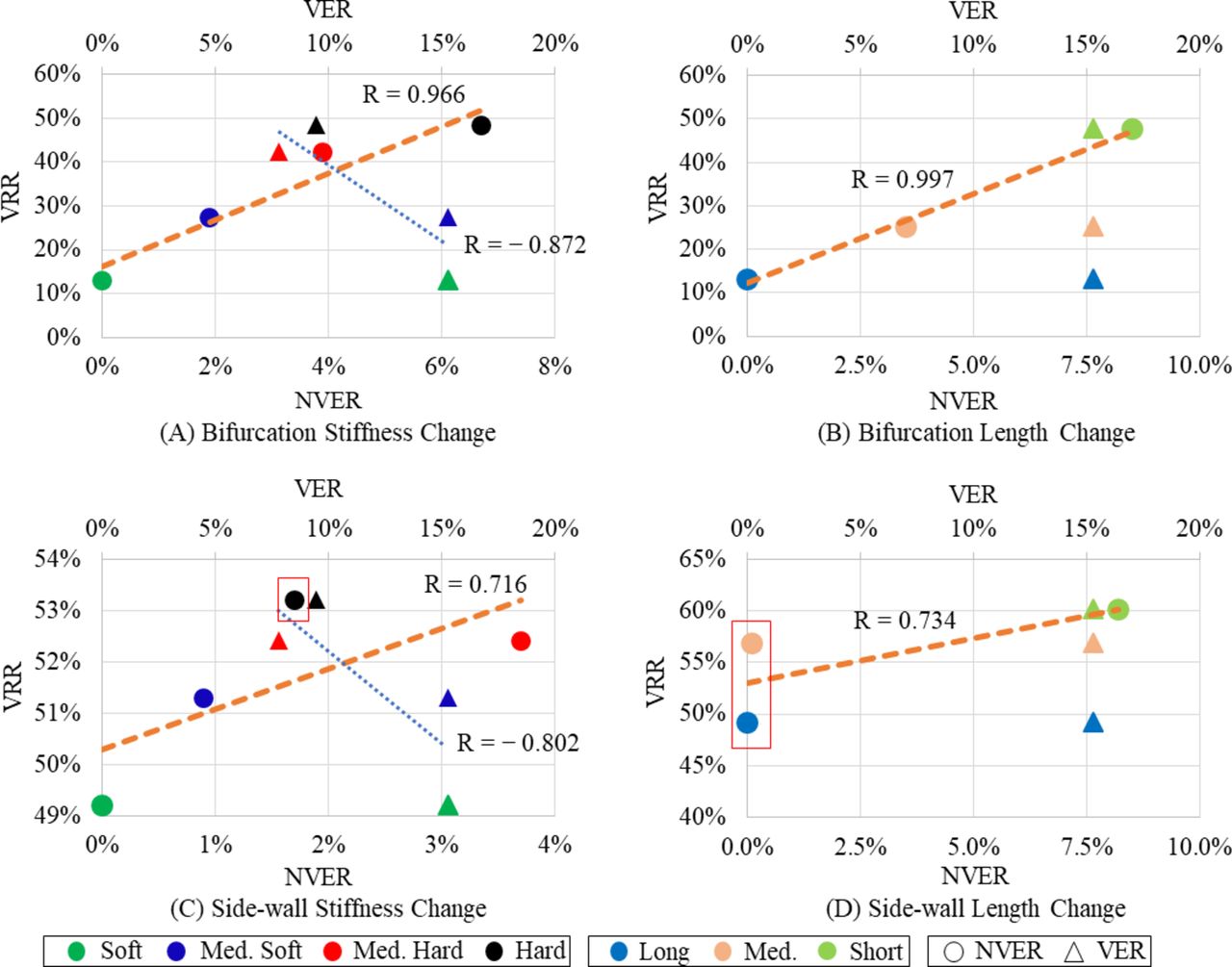
Figure 2 also shows hemodynamic differences among the cases. NVER, VRR, and WSSRR were observed in cases of the bifurcation type, as shown in table 1. While the hard coil compared with the soft coil raised NVER from 0% to 6.7%, a short coil increased the same parameters from 0% to 8.5%. VRRs also ranged from 13.0% to 48.4%. In addition, relationships between VRR and NVER or VER are shown as plot graphs in figure 3A, B. Regression lines and correlation coefficients are also shown. Positive correlations were identified between VRR and NVER in both graphs, with coefficients of 0.966 and 0.997, respectively. Conversely, VRR and VER showed negative (blue regression lines) or undefined correlations.

![[SP2.jpg]](https://jnis.bmj.com/content/neurintsurg/10/8/797/DC2/embed/inline-supplementary-material-2.jpg?download=true)
Relations between velocity reduction rate (VRR) and neck volume embolization ratio (NVER) or volume embolization ratio (VER). (A) Results of changing stiffness in the bifurcation type aneurysm. (B) Results of changing length in the bifurcation type aneurysm. (C) Results of changing stiffness in the side-wall type aneurysm. (D) Results of changing length in the side-wall type aneurysm. The red squares are specific examples of NVER/VRR values.
NVER, VRR, and WSSRR in side-wall type due to coil stiffness and length
NVER, VRR, and WSSRR of the side-wall type are also shown in table 1. While the hard coil compared with the soft coil raised NVER from 0% to 3.7%, a short coil increased the same parameters from 0% to 8.2%. VRRs also changed from 49.2% for the soft or long coils to 60.1% for short coils. In addition, the basic relationships between VRR and NVER and between VRR and VER were similar to those of bifurcation type aneurysms; the relationship between VRR and NVER was positive and between VRR and VER was negative or undefined (figure 3C, D).
Discussion
The basic aim of coil embolization is to block blood inflow into the aneurysm and obtain low velocity inside it, which results in thrombus formation with the inserted coils.22 23 To reach these ideal goals, VER was used as a popular metric to obtain sufficient velocity reduction because a high VER corresponds to a highly packed coiled aneurysm (blood cannot enter the aneurysm). In a study using CFD, Otani et al suggested that the stagnant volume ratio (SVR) quantifies the efficacy of coil embolization, which was modeled using porous media considering VER.24 Although they reported that a high SVR was mainly dependent on aneurysm angle related to the parent artery, flow changes were not described in relation to the difference in coil distribution, since the porous media used exerted uniform resistance to the flow in the aneurysm. Fujimura et al reported that coil distribution was closely related to velocity reduction in the aneurysm, but their research was only focused on side-wall type aneurysms.25
In this study, hemodynamics in the aneurysm were characterized before and after coil embolization in two types of basic aneurysmal models with changes in coil stiffness and length. Morales et al 26 reported that WSS and velocity magnitudes were reduced after coiling, as previously reported in a coiled aneurysm phantom using CFD technics and dynamic path planning virtual coiling.26 27 We also confirmed that the WSS and velocity were reduced after coil embolization. Although VRR changed due to VER, the relationship between them was not positive (eg, the correlation coefficient between VRR and VER was −0.872 in the bifurcation type due to coil stiffness). These results imply that effective velocity reduction is obtained with low VER, and NVER may be more useful to estimate the velocity reduction after coil embolization. In addition, coil stiffness and length affect coil distribution, which results in hemodynamic changes after coil embolization. It will be a great help for surgeons to know the coil characteristics for their operations to prevent aneurysmal recanalization (ie, which coil is more suitable for certain specific conditions).
Coil distribution in the aneurysm due to coil length and stiffness
Median values changed as a result of the changes in coil stiffness and length. More specifically, hard coils were mainly distributed at a median of 2.57 mm, medium hard at 2.48 mm, medium soft at 2.37 mm, and soft at 2.32 mm. In other words, harder coils enter the space closer to the aneurysmal wall, and softer coils enter the central spaces of the aneurysm. Similarly, the median value increased as the single coil length became shorter. These results were obtained because the restoring force of the hard coil is stronger than that of the soft coil, and the flexibility of the short coil is higher than that of the long coil. In addition, NVER, which represents the embolization ratio near the neck region, is higher when shorter coils are inserted because the short coil can easily enter tighter areas. This result implies that it is easier to make a short coil fill narrow areas such as the neck region.
Relationships between coil distribution and velocity reduction
For the bifurcation type aneurysm, although previous reports suggested a positive correlation between VER and velocity reduction, this was not confirmed in the present study; the relationship between them was negative with changing coil stiffness and length. On the other hand, NVER showed a good positive correlation with VRR in both graphs (figure 3A, B). This effective velocity reduction might be obtained because the inflow into the aneurysm was blocked with the high NVER, which indicates a high packing density near the neck inflow region.
In the same way, positive relationships were identified between NVER and VRR in the side-wall type aneurysm, but some irregular cases were seen (figure 3C, D). More specifically, although the NVER of a medium hard coil was higher than that of a hard coil, the VRR was higher in a hard coil. Similarly, although NVER was almost zero in both the long and medium coils, the medium coil obtained higher velocity reduction. The reason why the specific examples indicated in figure 3 were obtained is thought to be the difference in coil distributions within the aneurysm. As mentioned above, harder and shorter coils were more easily distributed at the outer side of the aneurysmal sphere. Both coils that obtain a higher VRR (hard and medium coils) were distributed at the outer side compared with the rest of the coils (ie, the medium hard and long coils). Basically, the blood flows along the aneurysmal wall after it enters the aneurysm. Since the outer distributed coils prevent blood flow more than the inner ones, a higher VRR is seen with the hard and medium coils.
Surgical decision-making and the present study
To achieve effective coil embolization, surgeons need to select the most suitable coil from a range of choices depending on the specific conditions. In actual clinical settings, hard and long coils are preferred for deployment in the outer side of the aneurysm. We have indicated that hard coils are suitable for entering the outer side of the aneurysmal dome; however, longer coils are mainly distributed at the inner side of the dome. This result might have been obtained because we did not consider the suitable single coil length for the specific aneurysm size (ie, we named the coils of different lengths as ‘long’, ‘medium’, and ’short’ dependent on their relative length, but the ‘long’ coil might be too long for a 6 mm aneurysm).
Considering our present numerical study, the hard coil is suitable to fill the outer side and the soft coil is preferred for the inner side of the dome. On the other hand, a short coil will be better to fill a narrow area such as the neck, which is an important region for blocking the blood inflow into the aneurysm. Specifically, deployment of a coil in the outer side of the aneurysm and at the neck is important to obtain sufficient velocity reduction. These strategies based on the basic coil characteristics and hemodynamics may help surgeons to perform effective coil embolization.
Limitations of the study
There are some limitations to the FEM and CFD analyses used in this study compared with actual coil embolization and blood flow. First, the speed of coil movement was fixed but it is not constant during actual coil embolization. We also should be aware that coil breaking inside the aneurysm is supposed to be the same provided boundary conditions do not change. Although different types of coils are used to treat actual aneurysms, we have not combined them in one simulation. Furthermore, we did not investigate the most suitable single coil length for the size of the aneurysm. The aneurysmal wall and catheter were assumed to be rigid and completely fixed, with the catheter tip always in the center of the dome sphere, but in reality this is often not the case. Thus, the aneurysmal shape was not changed and the catheter was not bent due to coil insertion. The limitation of rigidity is common to blood flow analysis using CFD. Although NVER should change chronologically by pulsation, in this study a steady mass flow rate was imposed at the inlet (ie, pulsation was not considered). NVER is a uniquely defined parameter. One of the main limitations of this study is how to apply NVER to actual aneurysms. In addition, we still need further research using coils of different brands. Since the Target 360 series coils were designed to break in a certain manner, the coils tend to be spread to the outer side of the aneurysm, unlike the Codman DELTAMAXX Microcoil (Codman & Shurtleff, Raynham, Massachusetts, USA). These irregularly bending coils may not follow the present findings with changes in their stiffness and length. Other detailed limitations are described in the online supplementary data.
Conclusion
FEM and CFD analyses were performed to simulate coil embolization and to characterize the hemodynamic changes that occur with different coil stiffness levels and length using Stryker 360 series coils. The results obtained in this study may be summarized as follows:
The harder the coil, the easier to enter the outer side in the aneurysmal sphere.
If the coil is short, it can enter tighter areas more easily, also making it easier to fill the neck region.
To obtain effective velocity reduction, a radial coil distribution with a high density near the aneurysmal wall and high NVER are important to prevent blood flow into the aneurysm in both side-wall and bifurcation type aneurysms.
References
Footnotes
Contributors All authors gave final approval of the published version and agree to be accountable for all aspects of the work in ensuring that questions related to the accuracy or integrity of any part of the work are appropriately investigated and resolved. SF, HT, and TS performed the simulations and collected and analyzed the data. CD, TI, HM, MY, and YM helped evaluate the data. SF and HT wrote the manuscript.
Funding This work was supported by Siemens Healthcare KK grant number 35993-00211563 and JSPS KAKENHI grant number JP17J07496.
Competing interests None declared.
Provenance and peer review Not commissioned; externally peer reviewed.
Data sharing statement The authors are willing to share spreadsheets from their data acquisition and experimental set-up details on request.