Article Text

Abstract
Although enthusiasm for transradial access for neurointerventional procedures has grown, a unique set of considerations bear emphasis to preserve safety and minimize complications. In the first part of this review series, we will review important anatomical considerations for safe and easy neuroendovascular procedures from a transradial approach. These include normal and variant radial artery anatomy, the anatomic snuffbox, as well as axillary, brachial, and great vessel arterial anatomy that is imperative for the neuroendovascular surgeon to be intimately familiar prior to pursuing transradial access procedures. In the next part of the review series, we will focus on safety and complications specific to a transradial approach.
- angiography
- intervention
- technique
Statistics from Altmetric.com
Introduction
Interest has burgeoned in the use of the radial artery as an access site for neurointerventional procedures because it has been associated with fewer complications, shorter hospital stays, and patient preference. Nevertheless, transradial access (TRA) presents a unique set of considerations to preserve safety, including intimate knowledge of the anatomical variations of the upper extremity arterial supply. Here, we aim to review normal anatomy and variants that bear relevance to neuroendovascular procedures performed via radial artery access.
Radial artery anatomy
Anatomic relationships
In the forearm, the radial artery’s first segment descends along the pre-axial border accompanied by a pair of radial veins (venae comitantes). The radial artery is covered by superficial and deep fasciae throughout the forearm, except in the upper segment where it is overlapped by the belly of the brachioradialis muscle (figure 1A). The radial artery’s middle segment runs in close proximity to the superficial branch of the radial nerve. Inferiorly, it runs between the brachioradialis laterally and pronator teres medially, then passes inferolaterally between the brachioradialis and flexor carpi radialis to reach the anterior surface of the distal end of the radius where the radial pulse is felt against bone (figure 1B). The presence of bone posteriorly should be verified sonographically when choosing the puncture site, because it significantly aids in radial artery puncture as well as manual compression to achieve patent hemostasis during closure (figure 1C).

Radial artery anatomic course. (A) Radial artery course in the forearm. In the proximal forearm segment, the radial artery is deep to the brachioradialis muscle. (B) Ultrasound image of the wrist during conventional transradial access over the lateral aspect of the radial styloid corresponding with the dotted line in (A). APL, abductor pollicis longus; EPB, extensor pollicis brevis; RV, radial vein. (C) Ultrasound image of the wrist during transradial access over the medial aspect of the radial styloid. Radial artery encircled in yellow. FCR, flexor carpi radialis. (D) Radial artery course through the anatomic snuffbox. (E) Ultrasound view of the anatomic snuffbox, corresponding with the dotted line in (D), identifying the radial artery (broken yellow circle), superficial branches of the radial nerve (red circles), cephalic vein (CV), and scaphoid bone.
The lower aspect of the middle segment of the radial artery curves over the radial aspect of the wrist joint, just beyond the styloid process to the first interosseous space. It passes under the long abductor (abductor pollicus longus) tendon and then travels between the long and short extensor of the thumb (extensor pollicus longus and extensor pollicus brevis) in the anatomic snuffbox (figure 1D,E). There, it is abutted dorsally by the distal scaphoid and trapezium, where the distal radial pulse can be palpated for anatomic snuffbox access, and is crossed superficially by the commencement of the cephalic vein (to be avoided during distal radial artery access) and superficial branches of the radial nerve.
In the hand, the last radial artery segment enters the palm by passing between the two heads of the first dorsal interosseous muscle. Then it turns medially, passes between the transverse and oblique heads of the adductor pollicis, continues across the base of the metacarpals, and joins with the deep branch of the ulnar artery to form the deep palmar arch.
Radial artery branches
From the first segment in the forearm:
The recurrent radial artery (RRA) arises laterally just beyond the radial artery’s origin, passes between the superficial and deep branches of the radial nerve, then ascends posteriorly to the brachioradialis and anteriorly to the supinator and brachialis, and ends by anastomosing with the branches of the deep brachial (profunda brachii) artery around the elbow joint. This branch is of particular relevance given its association with the brachioradial artery’s cubital crossover as well as the radial artery loop variant, both of which are further discussed below. As such, the RRA can be easily catheterized inadvertently when attempting to advance a wire from the proximal radial artery into the distal brachial artery, and is a common site of perforation.
The palmar carpal branch arises at the lower border of the pronator quadratus and anastomoses with the palmar carpal branch of the ulnar artery, anterior interosseous artery, and recurrent branches from the deep palmar arch to form the cruciate anastomosis over the anterior aspect of the carpal joint thereby providing collaterals in cases of radial artery occlusion/thrombosis. joint providing collaterals, in addition to the ulnar artery, in cases of radial occlusion/thrombosis.
From the second segment in the wrist:
The superficial palmar branch arises as the radial artery curves laterally around the wrist. It courses forward over the thenar muscles and anastomoses with the analogous branch of the ulnar artery to complete the superficial palmar arch. Of note, the superficial palmar branch arises proximal to the anatomic snuffbox used for distal radial access discussed in greater detail at the end of this section.
The deep palmar branch arises as the terminal part of the radial artery, anastomosing with the deep palmar branch of the ulnar artery to form the deep palmar arch that courses between the bases of the metacarpal bones and the long flexor tendons of the digits.
From the third segment in the hand:
The arteria princeps pollicis arises from the radial artery in the palm and gives rise to the nutrient artery to the first metacarpal bone.
The arteria radialis indicis arises from the proximal part of the arteria princeps pollicis.
Distal transradial access
While conventional radial artery access has been shown to have advantages over the transfemoral approach,1 2 its benefits may be further augmented by accessing the vessel within the anatomic snuffbox. This technique was introduced as a method to facilitate retrograde radial artery recanalization and has been increasingly adopted by interventional cardiology and radiology in recent years,3–6 with neurointerventional procedures now starting to show similar promise.7–12
Because distal TRA (dTRA) involves puncture within the anatomic snuffbox distal to the origin of the superficial palmar arch branch, the risk of hand ischemia resulting from radial artery occlusion is substantially reduced. If the radial artery occludes at the dTRA puncture site, the superficial palmar branch, arising proximally, continues to provide blood supply to the hand. Also, compared with the more proximal radial artery, the distal radial artery is more superficial relative to the skin, allowing for more rapid postoperative hemostasis. In addition, the puncture site location facilitates access with the wrist pronated (rather than supinated in conventional radial artery access), thereby enhancing patient comfort. dTRA access also permits wrist mobility during postprocedural hemostasis, while conventional radial access typically requires slight wrist extension during the postprocedural period.13
The anatomic snuffbox is formed by the abductor pollicis longus and extensor pollicis brevis tendons laterally and the extensor pollicis longus tendon medially. The carpal bones—namely, the scaphoid and trapezium—constitute the deep border. It contains the radial artery and vein(s), cephalic vein, and superficial branches of the radial nerve (figure 1D,E). The superficial branches of the radial nerve are typically not readily seen unless using a high frequency linear transducer probe, and inadvertent puncture can result in self-limiting pain. However, care should be taken to identify and avoid the cephalic vein as its double wall puncture en route to the distal radial artery increases the risk of developing an arteriovenous fistula.
Ultrasound guidance is strongly recommended over blind puncture. Radial pulsation is frequently more palpable distal to the snuffbox floor formed by the carpal bones, and puncture therein may hinder appropriate hemostasis given the lack of underlying bone to adequately compress against. Furthermore, ultrasound guidance allows assessment of distal radial artery size and avoidance of tendon puncture as well as double wall puncture causing hematoma formation and/or irritation of the underlying periosteum. A linear high frequency (>10 MHz) transducer is suggested to provide adequate spatial resolution, as the vessel is quite superficial. An ultra high frequency (6–18 MHz) ‘hockey stick’ type probe can be easily placed in the anatomical snuffbox due to its small size and allows excellent imaging of the distal radial artery, although one must be cognizant that because of its narrow field of view and built-in ‘step-off’, initial visualization of the needle as it traverses skin can be more difficult.
Radial artery size
The radial artery at its conventional access site has a mean diameter of 2.69±0.40 mm in men and 2.43±0.38 mm in women (range 1.15–3.95 mm).14 The ulnar artery is usually larger than the radial artery, contributes more blood flow to the palmar arch, and can provide a feasible access site in the context of radial artery occlusion. However, due to a deeper course and the wrist flexor muscles, hemostasis of the ulnar artery can be more difficult to achieve because of difficulty compressing it against the underlying ulna.15 16
Compared with the transfemoral approach, TRA is associated with a higher rate of access site arterial spasm and thrombosis/occlusion. Thus pharmacologic prophylaxis is typically used consisting of ‘cocktails’ containing calcium channel blockers (ie, verapamil), nitrates (ie, nitroglycerin), and heparin. TRA should be considered relatively contraindicated for patients with safe transfemoral access options whose radial artery diameter measures <2.0 mm or whose interventions require sheath sizes >6 French owing to high rates of radial artery spasm and occlusion.17 Access site decisions are best made on a patient-by-patient basis by assessing the size of the radial artery diameter using ultrasound, the sheath/catheter size needed for intervention, the anatomy and tortuosity of the aortic arch and great vessels, the indications for treatment, and the patient’s antithrombotic regimen. Of particular note, the distal radial artery in the anatomic snuffbox is only slightly smaller than its more proximal site. Although statistically significant, this minute difference does not typically require downsizing of sheath size to facilitate dTRA.18
Radial artery anatomic variants
Anatomic variations of the radial artery derive from the embryological development of upper limb arteries from an initial capillary plexus in a proximal-to-distal fashion, and result from the maintenance, enlargement, and differentiation of certain vessels with the regression of others. Table 1 summarizes the variants discussed in this review within the context of neuroendovascular procedures.
Anatomic considerations for transradial catheterization
Brachioradial artery
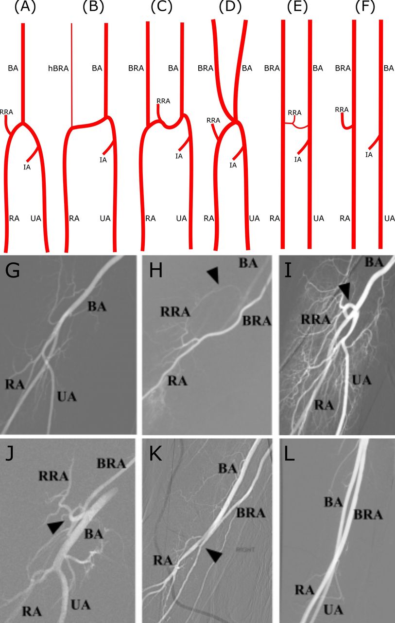
The brachioradial artery (BRA) has been used as the clear and unifying nomenclature for previously described terminology: ‘high origin of the radial artery’, ‘radial artery originating from the axillary artery’, ‘high bifurcation of the brachial artery’, ‘continuance of the superficial brachial artery as the radial artery’, and ‘double brachial artery’. ‘Brachioradial artery’ is a uniform term used for the colloquial ‘high origin of the radial artery’ proximal to the elbow from either the brachial or, less frequently, the axillary artery.19–21 An anastomosis can frequently be observed between the BRA and conventional brachial arteries in the cubital fossa known as a ‘cubital crossover’ or ‘cubital connection’, which has several variations19:
Conventional anatomy (figure 2A) with no BRA.
Dominant type of cubital crossover (figure 2B) with a hypoplastic pre-anastomotic part of the BRA (~9% of BRAs).
Balanced type of cubital crossover (figure 2C): anastomosis characterized by a similar diameter to that of the BRA (~27% of BRAs).
Arterial island (figure 2D): in rare cases, two arteries (BRA and brachial artery) may create an arterial complex (like an island) at the level of the radial neck, which ends in a division into radial and ulnar arteries. This extremely rare form lacks a reported incidence and is limited to isolated case reports.
Minimal type of cubital crossover (figure 2E): anastomosis narrower in diameter than the BRA (~18% of BRAs).
Absence of the cubital crossover (figure 2F): no anastomosis between the BRA and the conventional brachial artery within the cubital fossa (~45% of BRAs).

Radial artery anatomic variants. (A–F) Selected anatomical variations of the cubital crossover. (G) RA roadmap angiogram showing conventional anatomy. (H) Roadmap angiogram showing BRA anastomosis to the BA superior to the field of view. The RRA anastomoses to the BA in the cubital fossa (arrowhead shows cubital crossover). (I–J) Roadmap angiograms showing RA loops (arrowheads). (K) Small RA continuing superiorly as a BRA after a small anastomosis to the BA in the cubital fossa (arrowhead shows cubital crossover). (L) The RA continues superiorly as a BRA without a discernible cubital crossover to the BA. The BRA anastomoses to the axillary artery superiorly. BA, brachial artery; BRA, brachioradial artery; IA, common interosseous artery; hBRA, hypoplastic pre-anastomotic part of brachioradial artery; RA, radial artery; RRA, radial recurrent artery; UA, ulnar artery. Panels A–F reproduced with permission from Haladaj et al.19
The BRA presents as a risk factor for developing vascular complications of TRA.22 Thus the interventionist using the TRA route must discern these variants in order to perform catheterization and intervention in a safe and efficacious manner. Given the high prevalence of BRA at nearly 10%,19 subtraction angiography and roadmap guidance should always be performed at this location to avoid inadvertent wire perforation during retrograde catheterization of the brachial artery (figure 2G–L).
Radial artery loop
Radial artery loops represent a less common anatomic variant with a prevalence of approximately 1%.23 Just distal to the origin of the radial artery, they can be characterized by either the classic 360° loop (figure 2I) or merely marked tortuosity greater than 90° (figure 2J). The radial artery loop is invariably accompanied by the RRA, which assumes a straight path into the upper arm. Although they are not an absolute contraindication, radial artery loops can present a prominent hurdle to TRA and are associated with many TRA failures.24 Despite being a rarer anatomic variant, they are the most common cause of procedure failure for experienced TRA operators.25 Attempts to cross radial artery loops frequently lead to the wire entering the RRA, increasing the risk of dissection or perforation, especially in cases where the operator is not cognizant of this pattern of anatomic variation. Radial artery loops can often be straightened with a hydrophilic guidewire and 5 F catheter. If unsuccessful, a microcatheter system can be used with a stiff microwire to reduce the loop with the assistance of manual compression at the antecubital fossa, while taking care to avoid injuring or avulsing the less mobile RRA. Such maneuvers, however, may induce severe spasm and pain rendering successive catheter manipulation and advancement impossible. If a radial artery loop cannot be straightened, the RRA may be used to access the brachial and axillary arteries, provided that the RRA measures >2 mm, or an alternate access site can be chosen.23 24 26–28
Radial artery origin
The radial artery originates 1 cm distal to the flexor crease of the elbow as a terminal branch of the brachial artery in the cubital fossa at the level of the neck of the radius (figure 3). Although the figures used throughout this review illustrate right sided anatomy as the default access option, left sided access is feasible with proper room setup depending on the patient’s anatomy.29 The radial artery continues in the same direction as its parent trunk and extends from the cubital fossa to the palm, ending as an anastomosis with the ulnar artery to form the deep palmar arch, as described above.

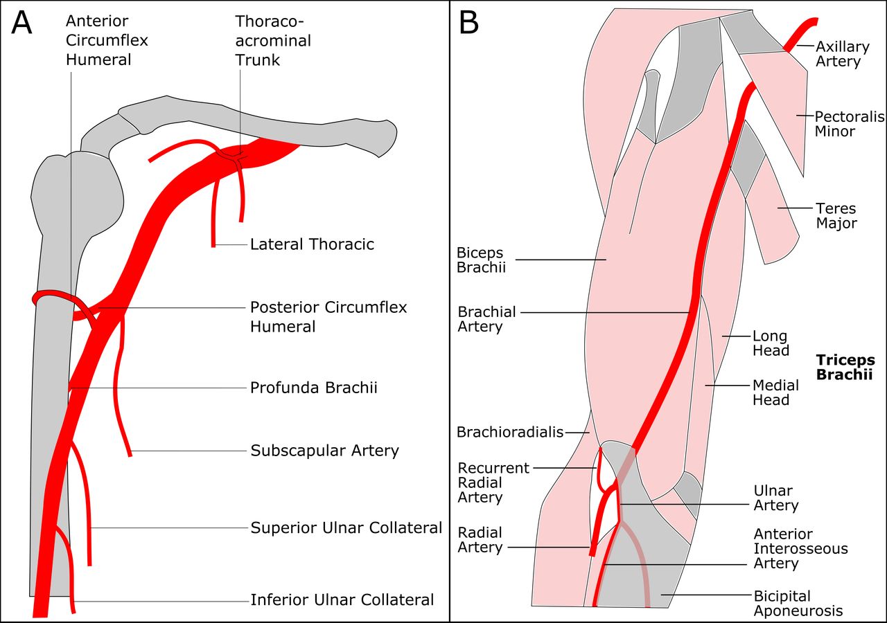
Upper arm arterial anatomy. (A) Branches of the axillary and brachial artery. (B) Brachial and radial artery course in the upper arm.
Axillary and brachial artery anatomy
Roadmap angiography is often of limited use in the brachial and axillary artery because significant retrograde opacification of these larger arteries can be difficult without power injection through 4 F catheters. Therefore, knowledge of the branches of the brachial and axillary arteries and their expected origins (figure 3A) is paramount to avoid wire perforation during retrograde catheterization. Fortunately, the branches of the brachial and axillary arteries have a relatively constant anatomic course, and the branch vessel origins are easily predictable in relationship to the underlying osseous anatomy. The axillary artery is divided into three segments. The first part of the axillary artery begins distal to the lateral border of the first rib and serratus anterior. The second part begins at the upper border of the pectoralis minor muscle, ending at the lower border of the pectoralis minor muscle. The third part begins at the lower border of the pectoralis minor muscle and ends at the lower border of the teres major (figure 3B).
Thoraco-acromial trunk: short artery arising from the second part of the axillary artery posterior to the pectoralis minor muscle that divides into clavicular, acromial, pectoral, and deltoid branches.
Lateral thoracic artery: travels along the lateral border of the pectoralis minor, then branches into perforators to supply the axillary lymph nodes, the serratus anterior, pectoral muscles, and subscapularis muscle, as well as breast tissue, often anastomosing with branches of the internal thoracic artery.
Subscapular artery: largest branch of the axillary artery arising from the third part and anastomoses with the lateral thoracic and intercostal arteries.
Circumflex humeral: wrapped around the surgical neck of the humerus and formed by an anastomosis between the anterior and posterior humeral circumflex arteries to supply the glenohumeral joint and head of the humerus. The posterior circumflex humeral artery courses through the ‘quadrangle’ space created by the teres major and minor, the long head of the triceps brachii, and the surgical neck of the humerus.
Deep brachial (profunda brachii): the first and largest branch of the brachial artery originating from the posterior portion; after giving off an ascending branch to supply the deltoid muscle, the deep brachial artery courses along the long and medial heads of the triceps brachii to supply the posterior upper extremity.
Superior and inferior ulnar collateral branches: anastomose with the anterior and posterior ulnar recurrent arteries to supply the elbow joint.
Brachiocephalic artery tortuosity
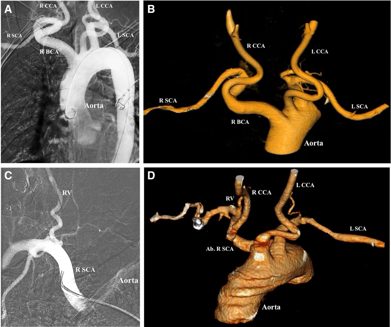
Normally, the brachiocephalic artery arises from the anterior part of the aortic arch and courses upward and to the right, bifurcating into the right subclavian and common carotid artery at the sternoclavicular junction. A tortuous course of the brachiocephalic artery may be seen in 25% of cases (table 1), with the artery coursing posteriorly and inferiorly before coursing anteriorly and bifurcating into its branches. The presence of multiple curves in the anatomy of the brachiocephalic artery, as seen in figure 4A,B, makes vessel selection of the carotid arteries more difficult because of a reduction in torquability of the wire or catheter.30

Aberrant right subclavian artery and tortuous brachiocephalic artery. (A) Tortuous right brachiocephalic artery (R BCA) which courses posteriorly and medially, branching into the right common carotid artery (R CCA) and right subclavian artery (R SCA). L CCA, left common carotid artery; L SCA, left subclavian artery. (B) Three-dimensional reconstruction demonstrating tortuous path of the right R BCA arising from the aorta. (C) R SCA which originates directly from the aorta, and courses anteriorly and superiorly to give off the right vertebral artery (RV). (D) Aberrant right subclavian artery (Ab R SCA) arises posterior to the L SCA and courses anteriorly and superiorly and gives rise to the RV. The R CCA arises from the aorta directly (origin not pictured here). The L CCA also arises directly from the aorta, anterior to the origin of the left subclavian artery.
Aberrant right subclavian artery
The right subclavian artery usually arises as a branch of the right brachiocephalic artery. However, in about 0.47% of cases,31 the artery may arise directly from the aortic arch posterior or distal to the origin of the left subclavian artery. The aberrant right subclavian artery courses posterior to the esophagus and courses anteriorly and upward towards the right upper extremity. In the case illustrated in figure 4C,D, the right common carotid arises from the aortic arch, and the right vertebral artery arises from the right subclavian artery. Occasionally, the right vertebral artery may arise from the right common carotid artery. The presence of an aberrant right subclavian artery significantly increases the difficulty of performing a right transradial catheterization of the great vessels, forming a relative contraindication, and should often prompt consideration of conversion to transfemoral access.
Great vessel anatomy
In normal aortic arch anatomy, the arch gives rise to three vessels, the brachiocephalic trunk, the left common carotid artery, and the left subclavian artery. A ‘bovine’ aortic arch variant gives rise to only two branches, with a common origin of the right brachiocephalic artery and left common carotid artery, accounting for 13.6% of aortic arches.32 The presence of a ‘bovine’ configuration of the aortic arch can significantly ease catheterization of the left common carotid artery from a right transradial approach. Understanding such arch anatomy is therefore important in preprocedural planning in determining the approach and tools. Preprocedural review of neck CT angiography or MR angiography in coronal and sagittal plane with 5–10 mm maximum intensity projection reformats can be helpful in this regard. If time permits, a three-dimensional volume rendering reformat of neck CT angiography or MR angiography data with 0.5–1.0 mm slice thickness can further facilitate catheter choice and preprocedural planning.
Conclusion
The radial artery provides an alternative, and in some ways more favorable, access site for the neurointerventionalist. However, certain anatomic features can relatively contraindicate TRA, particularly when patients have transfemoral access options or are not taking antithrombotic medication (that could increase the risk of an access site bleeding complication). Therefore, correct radial artery access demands the physician be well versed in identifying anatomical variants, weighing the risks and benefits of different closure techniques, and recognizing access site complications33. Important anatomic features include a radial artery diameter <2 mm, radial artery loops, a tortuous brachiocephalic artery, or an aberrant right subclavian artery. While the advantages of transradial over transfemoral catheterization have been established in the field of interventional cardiology with randomized controlled clinical trials, further study is warranted to directly establish its advantage in specific realms of interventional neuroradiology/neurointerventional surgery.
Supplemental material
Ethics statements
Patient consent for publication
References
Supplementary materials
Supplementary Data
This web only file has been produced by the BMJ Publishing Group from an electronic file supplied by the author(s) and has not been edited for content.
Supplementary Data
This web only file has been produced by the BMJ Publishing Group from an electronic file supplied by the author(s) and has not been edited for content.
Footnotes
Correction notice Since this article first published online some grammatical changes have been made for clarity.
Contributors KHN conceived of, wrote, and supervised the manuscript. MHM and MD provided literature review, wrote the manuscript, and provided figures. MTC, AB, and EAW provided critical feedback and review. RTH, VVH, MRA, DLC, SWH, AAA, and CFD provided supervision and feedback.
Funding KHN received funding from NIH NINDS U54 NS065705.
Competing interests None declared.
Provenance and peer review Commissioned; externally peer reviewed.
Supplemental material This content has been supplied by the author(s). It has not been vetted by BMJ Publishing Group Limited (BMJ) and may not have been peer-reviewed. Any opinions or recommendations discussed are solely those of the author(s) and are not endorsed by BMJ. BMJ disclaims all liability and responsibility arising from any reliance placed on the content. Where the content includes any translated material, BMJ does not warrant the accuracy and reliability of the translations (including but not limited to local regulations, clinical guidelines, terminology, drug names and drug dosages), and is not responsible for any error and/or omissions arising from translation and adaptation or otherwise.
Linked Articles
- New devices and techniques