Article Text

Abstract
Adoption of middle meningeal artery embolization in the management of chronic subdural hematomas has led to a renewed interest in dural vascular anatomy. The readily identifiable major dural arteries and potential hazards associated with their embolization are well described. Less emphasized are several levels of intrinsic dural angioarchitecture, despite their more direct relationship to dural based diseases, such as subdural hematoma and dural fistula. Fortunately, microvascular aspects of dural anatomy, previously limited to ex vivo investigations, are becoming increasingly accessible to in vivo visualization, setting the stage for synthesis of the old and the new, and providing a rationale for the endovascular approach to subdural collections in particular. In contrast with traditional anatomical didactics, where descriptions advance from larger trunks to smaller pedicles, we present a strategic approach that proceeds from a fundamental understanding of the dural microvasculature and its relationship to larger vessels.
- brain
- cranial nerve
- hemorrhage
- intervention
- subdural
Statistics from Altmetric.com
Introduction
General aspects of dural vascular anatomy and pathology
Based largely on gross anatomical observations drawn from cadaveric dissections, Dr Henry Gray concluded in his classic textbook that the dura mater was nearly avascular.1 Over the next century, the discovery of vessel specific stains and other visualization methods led to the demise of this misconception. Modern tools have continued to advance our knowledge of the anatomy and pathophysiology of dural based diseases.2–6
The dura has three layers, each of which is associated with a vascular network. From superficial to deep, there are periosteal, meningeal, and border zone layers. The corresponding vascular networks are named outer, transitional, and inner (figure 1). The periosteal layer of cranial dura is apposed to the inner table of the skull, and contains the outer arterial dural network, encompassing the middle meningeal artery (MMA) and its major branches. The network is a fractal-like structure covering the entire dura. Its primary anastomotic arteries range between 100 and 300 µm, 3 connect the major dural branches, and are readily visible angiographically (figure 2). There is substantial variation in the size and pervasiveness of these anastomoses—no different than in all things vascular (figure 2). The secondary anastomotic arteries, still in the outer layer and measuring 20–40 µm, link the primary ones and may be visible on DYNA CT or similar high resolution volumetric imaging, especially when pathologically enlarged (figures 2 and 3). Outer network vessels also participate extensively in supply of the skull—its angiographic enhancement can be difficult to differentiate from that of dura. Finally, several ex vivo studies suggest the presence of physiologic arteriovenous anastomoses/shunts in the outer layer, perhaps as large as 50–90 µm in diameter.3 In our opinion, shunts of this size should be angiographically demonstrable, however, we have not definitively encountered these yet, nor found convincing demonstration of their presence in the literature.

Normal and pathologic dural vasculature of the periosteal layer (PL), meningeal layer (ML), and border cell layer (BCL). (A, B) Main middle meningeal artery (MMA) branches such as frontal (~400–800 μm). (C) Arterial network in the walls of sinuses (variable size). (D) Meningeal branch supplying the skull. (E) Cutaneous branch supplying the skull. (F) Cutaneous branch supplying the skull and meninges. (G) Primary anastomotic network of the outer layer, connecting larger dural branches (100–300 μm). (H) Secondary anastomotic network of the outer layer (20–40 μm). (I) Penetrating vessels in the relatively avascular ML. (J) Normal inner capillary network in the BCL layer. (K) Proliferating border zone/inner network vessels in a subdural hematoma—the vessels are located within membranes (L) and on the inner surface of the hematoma (M), which is also frequently covered by a membrane. (N) Areas of leakage/extravasation. (O) Dural venous drainage into the diploic vein.

(A–H) Aspects of the intrinsic meningeal vasculature. (A) Wedge/flow control microcatheter injection in the petrosquamosal branch, visualizing numerous outer network anastomoses (arrows) with the frontoparietal branch anteriorly and posterior meningeal artery territory inferiorly. Also notice a transosseous link to the superficial temporal artery (broken arrow). (B) Single dominant frontoparietal middle meningeal artery (MMA) branch, showing multiple outer network vessels, several associated with active contrast leakage into hematoma (oval); arrows mark arteries in the wall of the superior sagittal sinus. (C, D) Example of poor outer layer collaterals. Arrowhead points to petrous branch, which in the lateral view is superimposed on the petrosquamosal branch (arrows); also note the MMA supply to the skull (open arrows), producing skull, not hematoma, enhancement. (E–H) Same case; despite flow control contrast injection (E) failing to cross the midline, subsequent dilute n-butyl cyanoacrylate (nBCA) injection (F–H) shows the presence of multiple cross midline connections, also permeating inferiorly into the posterior meningeal territory. An arterial network in the wall of superior sagittal sinus (arrows) is well seen also (G, H).

(A–G) Advanced visualization techniques. (A) Volume rendered views of dual volume DYNA CT, subtracting non-contrast mask phase from the middle meningeal artery injection arterial phase in a patient with a subdural collection. The meningeal outer network is well seen. Patchy areas of hematoma membrane enhancement are also present. Stereo anaglyph (B) and stereo cross eye (C, D) views show these enhancing patches to be located in the inner capillary network, deep to the outer network vessels. (E, F) DYNA CT of the primary and secondary outer layer networks in the falx (E) and tentorium cerebelli (F) in the same patient—note arteries in the walls of the sinuses (arrowheads). (G) n-Butyl cyanoacrylate cast in the falx cerebri of case (E–H) in figure 2, also showing all too excellent penetration. Be careful….
From the outer periosteal network, penetrating vessels of the transitional network descend through a truly hypovascular meningeal layer to supply a dense capillary inner network, located in the innermost border zone layer, where cells of the same name closely adhere to the arachnoid. Vessels within this capillary sized network have a characteristic parallel appearance, measuring about 10 µm in diameter. The majority of subdural hematomas arise within the inner capillary layer, enlarging in a cycle of hemorrhage, hyperproliferation, fragility, and re-hemorrhage.7 8
No less an authority than Virchow described what we now know as subdural hematoma as pachymeningitis hemorrhagica interna, suggesting an inflammatory etiology.9 10 Later, this view was largely abandoned in favor of the torn bridging vein hypothesis. While this may be valid for major trauma, notably the non-accidental neonatal type,11 the theory has suffered from inconstant association with demonstrable trauma, indefinite demonstration of recognizably torn bridging veins (on intraoperative or post mortem inspection), and the simple improbability of frequent ruptures in a tiny potential space. Nevertheless, 'minor trauma' continues to be seen as an important inciting, if not recurrent, event in hematoma pathogenesis.
On the other hand, in 1965, Rowbotham and Little, in a seminal paper, wrote: “Clinically there are two types of subdural hematomata, one being due to traumatic rupture of the superior cerebral veins as they cross the subdural space to enter the superior sagittal sinus. In this group the prognosis following surgical drainage is good. In the other type, however, no history is obtained of trauma and the outlook following surgical drainage is poor. We suggest here that this second group of hematomata arises from oozing from the inner dural plexus, an idea which is supported by repeated small bleeds which are known to occur in these cases. The reason why prognosis is poor following surgical drainage is because the compressional factor is minimal, the dominant pathology being degenerative vascular changes within the brain tissue itself.” 2 This long quote is a beautiful example of how anatomical advances lead to informed disease insight.
The idea of chronic subdural hematoma (cSDH) as a product of recurrent bleeding within the inner layer is supported by multiple studies.5–7 12 13 Indeed, the membranes frequently seen within the hematoma, as well as on its inner surface, are composed of border zone cells and proliferating, fragile inner layer vessels—not 'naked' clot against the arachnoid—establishing the hematoma as, at least histologically, intradural (figure 1). This is by no means a fringe view.6 13 14 While we invite the reader to look deeper into the notion of classical three layered meninges, and particularly the dura–arachnoid junction,15 16 certainly for historical and practical reasons the 'subdural' hematoma will continue to be referred to as such.6 13
The notion of subdural hematoma resulting from repetitive, indolent inner layer hemorrhage naturally suggests embolization as a management strategy, first reported by Mandai et al in 2000 17 and more recently highlighted in multiple publications and reviews.18–28 We may also wonder whether a straightforward procedure such as MMA embolization, with a two decades long trickle of encouraging reports,29–31 would have gained attention sooner had the prevailing idea of bridging vein rupture not been adhered to as devoutly, or had the long existing literature on true pathogenesis been better known in the endovascular community.
Meningeal venous system
While the genus specific pattern of meningeal veins on the endocranium is well known to paleontologists,32 33 dural venous anatomy receives almost no attention in the medical literature, despite Padget’s seminal work outlining many anatomical features that now can be observed angiographically.34 The role of the meningeal veins in the evolution of subdural hematoma remains unclear. For example, to what extent do inner layer veins contribute to the bleeds? Are the aforementioned physiologic arteriovenous shunts fact or artifact? Fortunately, these questions seem to have no immediate implication on transarterial embolization.
Angiographic aspects of dural vascularization
Inner network
The normal inner capillary network, composed of vessels of about 10 µm diameter, is below angiographic resolution. When chronic subdural collections are present, the varied patterns or enhancement are likely those of a pathologically thickened and hyperemic inner layer (figures 3 and 4). If imaged during active microhemorrhage, characteristic pooling of contrast can be seen (figure 4A–C) on DSA. Variation in the degree of membrane enhancement may be due to differences in membrane stage, size, and proliferative activity (figure 4D–I).

(A–I) Inner layer network and membranes. (A–C) Case No 1. (A) Classic acute on chronic subdural CT. (B, C) Extreme example of multiple foci of membrane enhancement and active extravasation. (D–I) Case No 2. (D) Bilateral collections, more active on the right. (E, F) MIP reconstructions of right middle meningeal artery (MMA) injection DYNA CT showing inner layer membrane enhancement. (G) Lower image of same patient. (H, I) Left MMA injection DYNA CT, showing minimal membrane enhancement (arrowheads). In the meantime, contrast is diffusing into the right subdural collection (arrows) following its immediately preceding embolization.
Outer network
The primary anastomotic vessels, approximately 100–300 µm in diameter, are large enough to allow for small particles and liquid embolic agents to penetrate into adjacent vascular territories. 'Wedged' microcatheter position can be used to establish flow arrest conditions within the catheterized vessel distal to the microcatheter tip and is particularly useful as part of an embolization strategy (figure 5).37 The outer arterial network anastomoses across midline (figure 2F–H) with corresponding branches of the contralateral fractal outer network serving as both potential access to and a possible revascularization route for the contralateral convexity hematoma. Outer layer arteries also supply the skull (figure 2C,D); its enhancement may be difficult to differentiate from that of the dura.

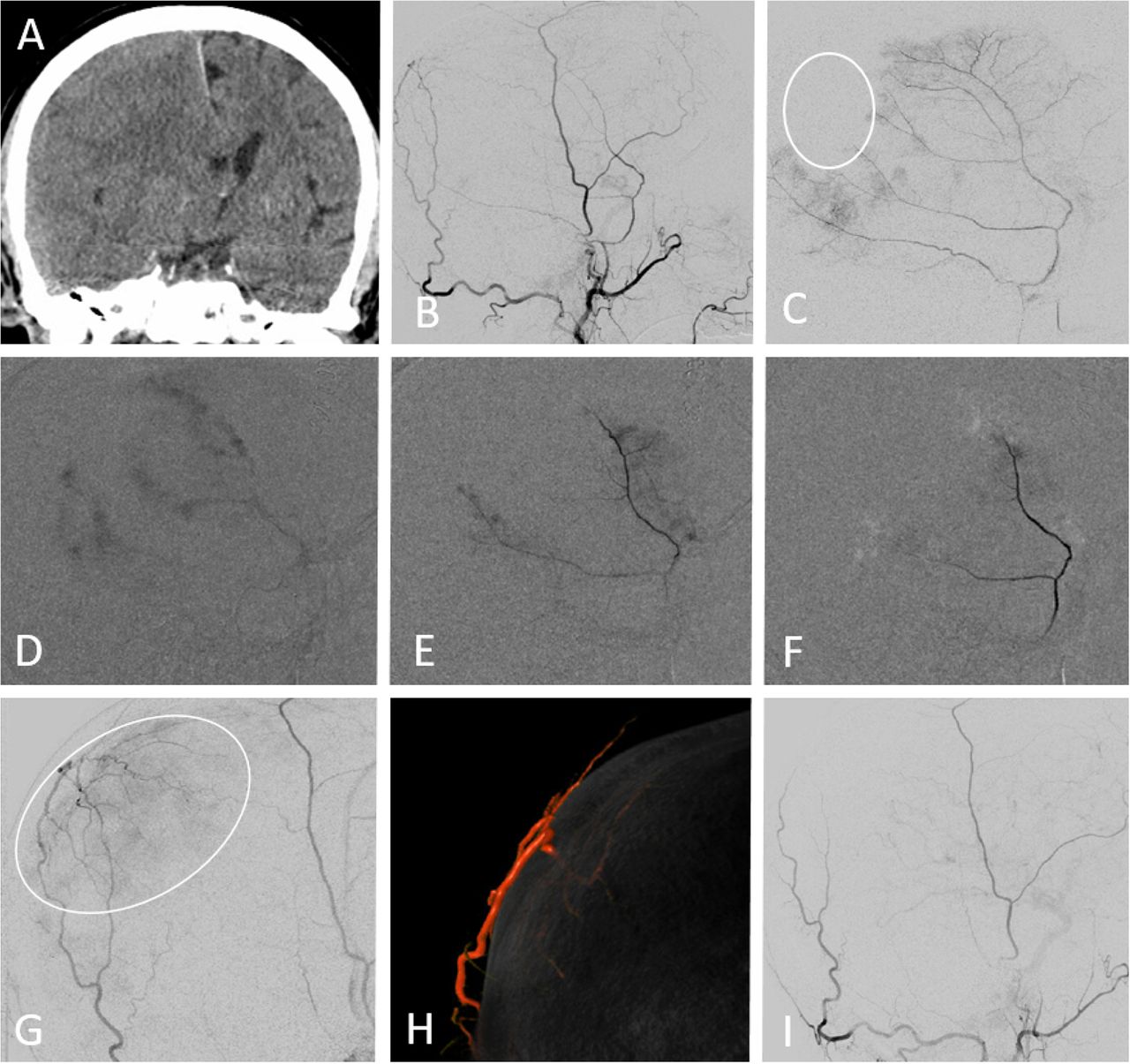
(A–H) Subdural embolization in the setting of bilateral recurrent meningeal artery dispositions. (A, B) Bilateral subdural collections. (C, D) Recurrent meningeal arteries supplying the frontal dura on the left (C, white arrow) and right (D, black arrow) sides (see figure 2A–D). (E) Left petrosquamosal branch 'wedge position' injection opacifying part of the frontal branch territory (white arrow) via several primary outer layer network anastomoses (arrowheads). This allows for partial embolization of territory principally supplied by the ophthalmic origin frontal branch. (F) On the right side, similar connections are not demonstrated and embolization is limited to the posterior middle meningeal artery territory. Note several venous lakes in the walls of the sigmoid and superior petrosal sinuses (arrows). (G, H) Delayed scan, showing complete resolution of left convexity collection, and persistent right frontal collection, with a small new hemorrhage (open arrow).
Both ex vivo and angiographic studies point to the consistent presence of discrete arteries or arterial networks in the walls of major venous sinuses (figures 2 and 6). These channels strategically link multiple arterial territories, and play an important role in the angioarchitecture of dural fistulas. Apart from proximity to the jugular foramina, they are located well away from cranial nerves, and can be useful vascular routes for embolization (figure 6E–H).

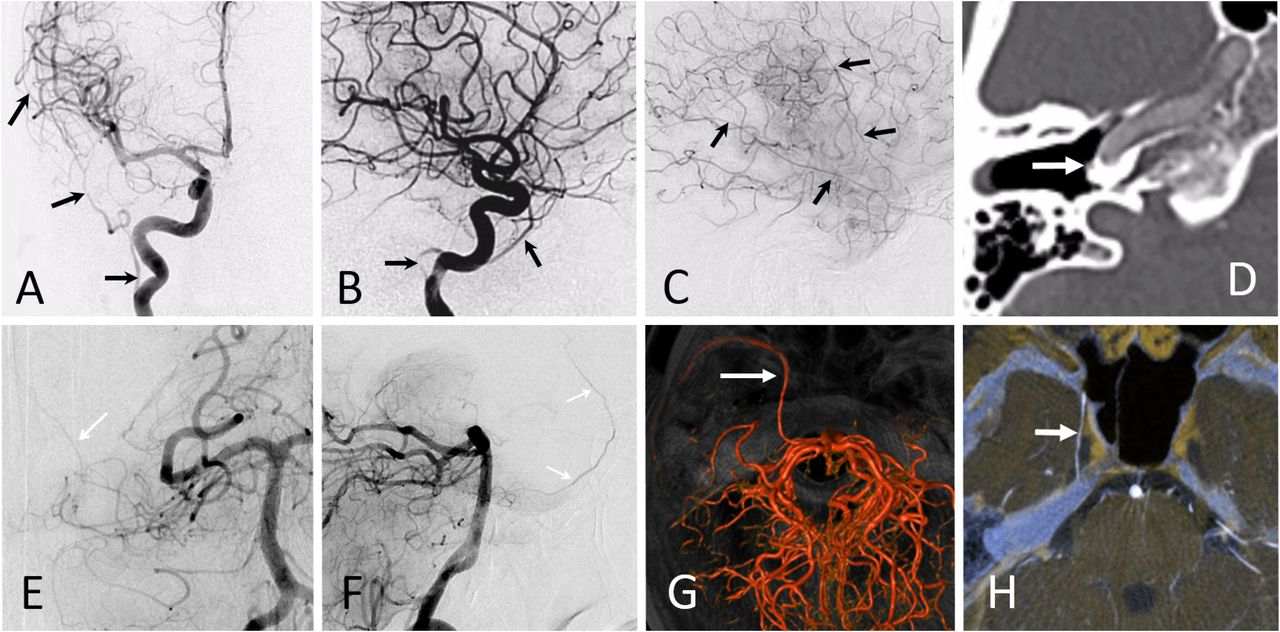
(A–H) Arterial network in sinus walls. (A) Schematic, used with permission from www.neuroangio.org. (B) Double mask common carotid artery injection showing occipital origin jugular branch visualizing the arterial channel in the wall of the sigmoid sinus heading towards a dural fistula (arrow). (C) Pial to dural anastomoses outlining arteries in the wall of transverse (black arrow) and sigmoid (white arrow) sinuses, also supplying a dural fistula (pink arrow). (D) Posterior meningeal supply to artery in the wall of the straight sinus (arrowheads) in a patient with falcotentorial junction fistula (arrow). (E–H) Same patient. Ethmoidal dural fistula, with prominent supply via paired arteries in the wall of the superior sagittal sinus (same as anterior meningeal arteries). This allowed for endovascular access to the fistula, followed by its closure with Onyx-18 (G, H).
The secondary network of the outer layer (below 50 µm) can be demonstrated in the falx cerebri and tentorium cerebelli on three-dimensional imaging (figure 3), correlating with ex vivo work by Roland et al 4 and others. These vessels are presently not as well visualized over the convexity, likely due to obscuration by the adjacent skull.
Primary MMA branches
Continuing the journey from distal to proximal, the main meningeal branches are variably named for the territories they supply: frontal, parietal, and petrosquamosal or anterior and posterior.38 All manner of variation is seen, with dominance of one at the expense of another, common origins, etc. Occasionally, the classic MMA territory is encroached on by the posterior and anterior meningeal or transosseous branches of the occipital and superficial temporal arteries supplying parts of the dura (figure 7). To what degree these collaterals contribute to dural revascularization and perhaps failure of embolization is currently unknown.
(A–I) Another instance of variable supply to the dura. (A) Classic CT 'isodense' subdural collection. (B, C) ECA (B) and middle meningeal artery (MMA) (C) injections showing a portion of parietal dura (white oval) supplied by occipital artery. (D–F) 'Pruning' of dural membrane enhancement during 45–150 μm diameter contour PVA embolization. (G) ECA injection post MMA EMBO demonstrating the extensive territory (oval) of the transosseous occipital supply to the dura and skull. (H) Dual volume rendered image showing the transosseous branch, principally supplying the dura. (I) Post additional particle EMBO—the microcatheter was advanced to the transosseous branch to minimize cutaneous embolization.
Petrous and cavernous branches
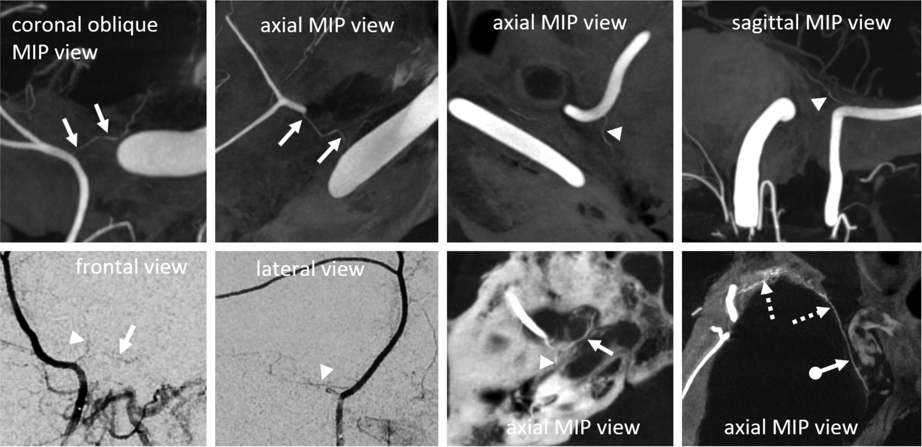
The frequently discussed petrous and rarely mentioned cavernous branches of the MMA are usually very small and originate immediately after the MMA emerges from the foramen spinosum (figure 8). Sometimes, the petrosquamosal branch is mislabeled as petrous, as the former projects over the petrous bone in lateral views. Frontal projections are very helpful, as the MMA tends to turn laterally inside the skull before giving off the petrosquamosal branch, whereas the more proximal, small petrous branch projects superiorly (figures 2 and 8). On lateral DSA views, the petrous branch is frequently obscured by very dense petrous bone and the superimposed petrosquamosal branch; however, it is better seen on good quality DYNA and rotational angiographic acquisitions. Supply to the facial and petrosal nerves can also arise from the accessory meningeal artery (figure 9) or the stylomastoid branch (occipital artery or posterior auricular artery origin), or a combination thereof.

DYNA CT MIP and DSA examples of petrous (arrowheads), cavernous (arrows), and tentorial arcade (ball arrow) branches in different subjects. Despite their small size, most can be resolved on high quality DSA images. The very rare tentorial arcade variant links the sphenoid branch (broken arrows) to the tentorial arcade, extending into the cavernous sinus — a much longer route than via the cavernous branch. Dense carotid calcification helps with localization.

(A–I) Importance of anatomy and technique in the evaluation of the meningeal circulation. (A) Left frontal subdural collection. (B) Global external VR view showing separate origins of the frontoparietal (anterior, white arrows) and petrosquamosal (posterior) dural branches from the internal maxillary artery. The frontal branch 'arises' from the accessory meningeal artery (AMA). (C) Middle meningeal artery (MMA) injection shows supply to the posterior branch. (D, E) Proximal AMA injection demonstrating supply to the frontal dura; no apparent orbital communication. (F) DYNA CT axial reconstructions of the same proximal injection showing supply of the petrosal and facial nerve arterial arcade (white arrow). Notice the catheter in the foramen ovale (black arrow), thus a too proximal embolization risks CN V injury. (G, H) A more distal injection under 'flow arrest' conditions now shows previously not visualized connection with the ophthalmic artery (black arrow) via the artery of the sphenoid ridge (white arrow). (I) DYNA CT axial reconstructions of same injection.
The cavernous branch of the MMA, projecting medially on frontal views, anastomoses with the posterior branch of the inferolateral trunk, thus making it both a potentially dangerous EC-IC anastomosis and a possible source of supply to Meckel’s (trigeminal) cave and its nerves (figure 8).39
The safest policy is not to embolize from a position proximal or near the foramen spinosum, both for the sake of these branches and the subsequently discussed orbital anastomoses. If proximal embolization is necessary (and no orbital collaterals are present), in our opinion, particles are safer than liquid embolic agents as far as cranial nerves are concerned.
Variant MMA origins
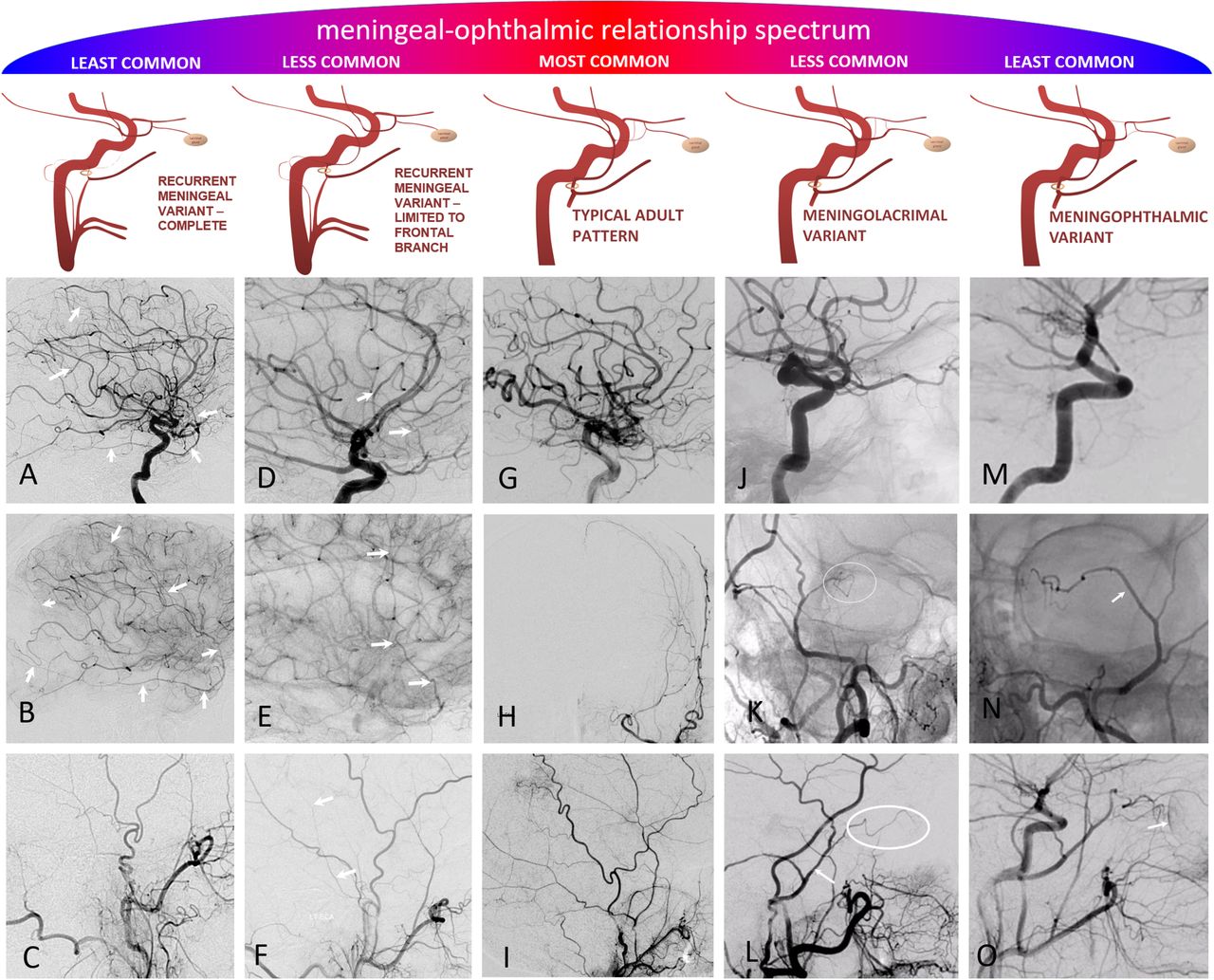
We emphasize a global approach to understanding the spectrum of MMA variations, particularly as they involve the ophthalmic artery, shown in figure 10. Any two interconnected vascular territories show variable balanced, partial, or complete dominance of one territory over another, with extremes being progressively rarer. The AICA-PICA and PCOM-P1 relationships are common examples. Middle meningeal–ophthalmic relationships follow the same principle.

(A–O) Meningo–ophthalmic relationships, emphasizing the 'spectrum' principle. Balanced typical adult pattern is the most common, followed by partial annexations of either ophthalmic territory by the middle meningeal artery (MMA) (recurrent meningeal frontal branch only) or vice versa (meningo-lacrimal variant), followed by the least common complete annexations (meningo-ophthalmic and complete recurrent meningeal variants). (A–D) Complete middle meningeal origin from the ophthalmic artery (white arrows, (A, B)). No MMA is seen from the external injection (C). (D–F) Ophthalmic origin supply of frontal dural branch only (arrows (D, E), best visible in parenchymal phase of brain injection), with some part of the middle meningeal supply still arising from usual IMAX location (arrows (F)). (G–I) Typical adult pattern. (J–L) Classic meningo-lacrimal variant. The lacrimal branch characteristically projects over the superolateral orbit in frontal view (oval (K)), and extends anteriorly on the lateral view (oval (L)). (M–P) Meningo-ophthalmic variant—essentially complete supply of orbit via the MMA, with no visible ophthalmic artery on ICA injection (M). if only common and external injections are done prior to MMA EMBO, it is best to look for a prominent vessel overlying the orbit, with medial extension, on frontal view (arrow (N)) and choroidal blush on the lateral view (arrow (O)).
A relatively common variant, at ~0.5% incidence in the literature,38 40 but about 2% in our experience, is recurrent meningeal origin from the ophthalmic artery. As mentioned above, there is a spectrum: the recurrent branch most often supplies only part of the frontal dura (figure 10D–F), less commonly a larger frontoparietal portion (figure 5), or rarely the entire MMA territory (figure 10A–C).41 We have not observed any correlation between the presence of a recurrent meningeal variant and cases of cSDH presenting for MMA embolization.40 Less common origins of the MMA are also well described in the literature (figure 11).38 42
(A–H) Rare but still useful variants to know. (A–D) Pharyngostapedial variant— early embryonic origin of the middle meningeal artery (MMA) from the stapedial artery (petrous segment origin, arrows (A, B, C)) with a highly characteristic course between the two crura of the stapes and over the cochlear promontory (D). Most patients have no pulsatile tinnitus or other clinical issue. (E–H) Basilar artery origin of the MMA —in fact this is a trigeminal artery to the MMA connection, as evidenced by its course alongside the trigeminal nerve on volume rendered (G) and fused DYNA CT and T1 axial MR images (H).
The recurrent meningeal dural supply proportionally reduces or eliminates the territory available for non-ophthalmic routes of embolization, possibly accounting for some procedural failures (figure 5).43 The 100–300 µm primary anastomotic arteries may be large enough to allow at least partial embolization of recurrent meningeal territory from adjacent vascular beds. This can be achieved by employing a 'wedged' microcatheter position to hydraulically push small particles or liquid embolic agents through the anastomoses.
MMA–orbital anastomoses
Our training program emphasizes identifying the ophthalmic artery in every angiogram. Whenever meningeal vessels supplying a lesion require embolization, there is potential for an ophthalmic complication, be it a subdural collection or torcular fistula.
The classic descriptions are of meningolacrimal and meningophthalmic variants. In the former, more common disposition (~5%), the MMA supply is limited to lateral orbital contents, entering the orbit via the foramen of Hyrtl (figures 10J–L and 11).42 In the latter, rarer variant (<1%), MMA supplies the entire orbit (figure 10M–O). In reality, these variants are not binary entities, but again part of a spectrum that includes a number of ophthalmic/middle meningeal anastomoses, usually linked by the sphenoid branch. This strategically positioned artery, like a railroad line, rides the sphenoid ridge, linking the frontal territory of the MMA with the inferolateral trunk region via the tentorial arcade.42 Traveling from the MMA, the first connection on the sphenoid branch railroad is with the lacrimal branch, forming the most common meningolacrimal variant. The next major connection, more distal and supplying more territory, and therefore less common, is with the ophthalmic artery, forming the meningophthalmic variant. Finally, the least common disposition is the last stop on the sphenoid line, where a transfer to the tentorial arcade railroad takes the rare traveler beyond the ophthalmic anastomosis all the way to the cavernous sinus, into an area usually supplied by the inferolateral trunk (figure 8). Inadvertent embolization in this variant, as in the case of the aforementioned cavernous branch, risks both cranial nerve injury and penetration into the ICA.
Visualization of these connections is a complex function of their developmentally determined and physiologically modified size, flow direction, catheter position, injection pressure, manipulation related (and therefore dynamic) vasospasm, resistance of overall vascular bed, and its change during embolization, etc (figure 9). Visualization may be further hampered by patient movement. Pragmatically, the possibility of MMA–ophthalmic connections should always be kept in mind, even if it is not readily appreciated during non-selective angiography.
Dural–pial autosynangiosis
Autosynangiosis refers to the parasitization of the extracranial dural supply by the subjacent pial surface44 and may be observed in settings of chronic cerebral ischemia or arteriovenous shunts. The presence of a fluid collection barrier between the dura and pia might argue against the possibility of autosynangiosis, however, we did come across an example (figure 12). Appreciation of the specific vascular anatomy should be noted, and care must be taken to avoid non-target embolization in these unique cases.45

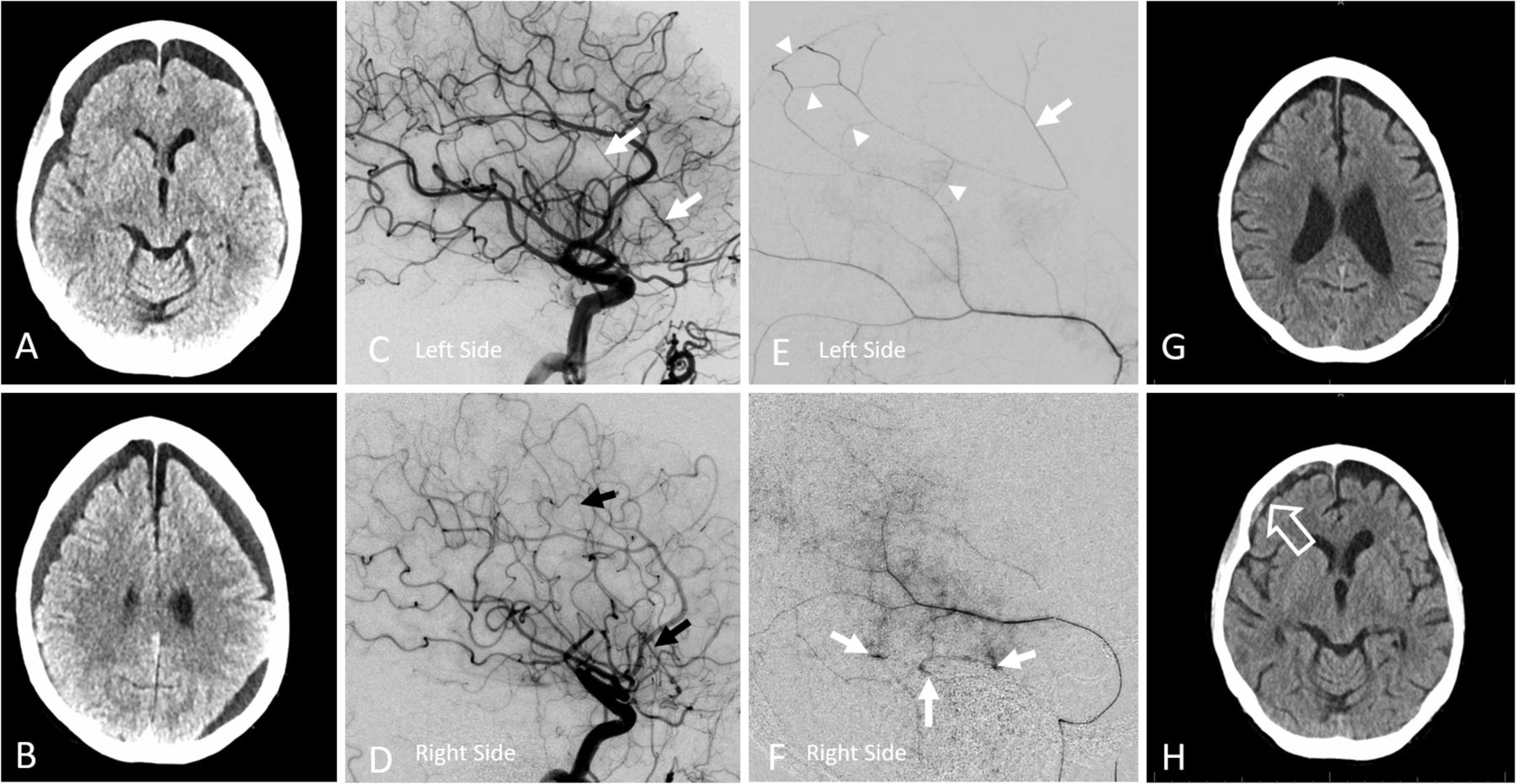
(A–H) Subdural collection in the setting of ischemia related autosynangiosis. (A, B) Predominantly hypodense subdural collection in a patient with remote right middle cerebral artery (MCA) infarct. (C, D) Two months after images in (A, B), the overall collection has shrunk but there is a new inferior frontal component. (E, F) Early arterial (E) and venous phase (F) images of right internal carotid artery injection, demonstrating chronic MCA occlusion, and a region of relative hypoperfusion in the right mid-frontal convexity. (G, H) Lateral and frontal projection ECA images show an autosynangiosis between the frontal branch of middle meningeal artery (MMA) and mid-frontal superior division MCA territory, matching the hypoperfusion area seen in (F). Thus non-targeted MMA embolization in this case would result in a right frontal infarct. Case courtesy of Dr David Gordon, NYULMC.
Technical aspects of embolization
Many approaches have been described. Exposure to preoperative tumor embolization varies widely in fellowships, and MMA embolization is likely patterned after these protocols. Whether, and when, ongoing randomized studies will help establish its safety and efficacy, as well as determine the optimal embolization agent(s) and technique(s), remains to be seen (table 1). Absent randomized trials or guidelines, we include a short description of our strategy.
Summary of embolic agents21 47–51
Common carotid angiography is followed by external carotid and then dedicated MMA views. If an orbital supply is not demonstrated, relatively proximal particle embolization (distal to the petrous/cavernous branches) is usually safe, diligently observing for covert orbital anastomoses as embolization progresses. In general, particles tend to penetrate evenly into a target territory, to an extent determined by their size relative to recipient vessels, while liquid embolic agents for complex reasons tend to select some paths over others, thus advancing further than particles into some areas and not as much into others. While we favor small particle size (45–150 µm) to maximize penetration, many operators prefer larger sizes to minimize the probability of non-target embolization. From an anatomical perspective, anything larger than 300 µm may not effectively penetrate beyond the main trunks, and in our opinion is suboptimal. At the end, we prefer to seal the trunk with coils. Pushable fiber coils require a larger diameter (0.021 inch) delivery microcatheter but are an order of magnitude cheaper than detachable coils, and highly effective.46 47
When orbital connections are demonstrated, we prefer selective catheterization of the frontal branch distal to the orbital supply (figure 13A–D). Anything above the orbital roof is likely safe. If there is still flow around the microcatheter, particles can be used (minimizing reflux), followed by coil occlusion. If there is a 'wedge' or 'flow control' position, we favor liquid embolic agents. The transient plug created by this technique allows the penetration of liquid embolic with minimal or no reflux and increases the ease of microcatheter removal after injection. To further minimize reflux, a dual lumen balloon microcatheter is an excellent choice.
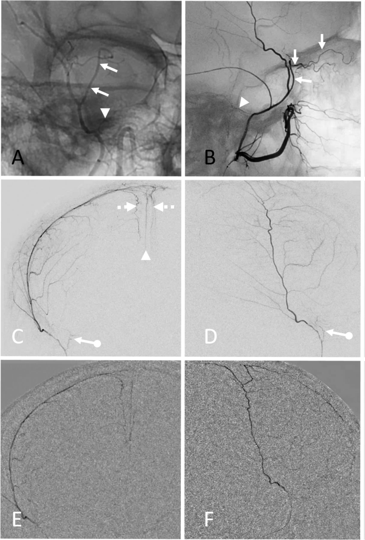
(A–F) Strategic use of liquid embolic n-butyl cyanoacrylate (nBCA) in the setting of orbital anastomosis. (A, B) Middle meningeal artery (MMA) angiography with a large meningolacrimal variant (arrows, also see figure 10J–L) contributing to the supply of the superior orbit and cutaneous tissues. Note also a relatively large petrous branch (arrowheads). (C, D) DSA of frontal branch distal to the origin of the meningolacrimal artery using a Scepter C balloon microcatheter. The balloon is inflated to eliminate reflux. Note penetration of contrast into the arterial arcade of the superior sagittal sinus (broken arrows) and falx cerebri (arrowhead). Also present is a frequently seen dural branch along the superolateral orbital rim (ball arrows)—it is not a meningolacrimal branch. (E, F) nBCA: Lipidol 1:2 cast, injected with Scepter C balloon inflated, achieving excellent penetration into target arteries as well as into potential collaterals of the anterior meningeal artery and contralateral MMA. The posterior (temporo-occipital) branch was also subsequently embolized.
Conclusions
Anatomical considerations support the rationale for MMA embolization in cSDH. The questions of efficacy and treatment durability will hopefully be answered by randomized controlled trials in the near future. If MMA embolization is confirmed to be an effective overall strategy, we must also investigate why it sometimes fails. The optimal embolic agent(s) remain unknown, and techniques vary widely, however anatomy does guide choices in individual patients. From a cost perspective, particles with or without pushable coils are clear winners in most contexts. Imaging advances will continue to enhance our understanding of the dural vasculature, and with that future angiographic interventions.
References
Footnotes
Twitter @DrMichaelLevitt, @ozmir1
Collaborators Jonathan Dimes jonathan@jdimesmedivisual.com.
Contributors All authors contributed to writing and review of the manuscript.
Funding The authors have not declared a specific grant for this research from any funding agency in the public, commercial, or not-for-profit sectors.
Competing interests MS is a consultant to Medtronic. MW is an educational consultant to Medtronic. MRL receives unrestricted educational grant funding from Medtronic and Stryker, is a consultant for Medtronic, and holds equity interest in Cerebrotech, Synchron, and Proprio.
Provenance and peer review Commissioned; externally peer reviewed.