Article Text

Abstract
Background The Enterprise (EN) vascular reconstruction device is a self-expanding nitinol stent used as adjunctive support in wide-necked aneurysm coiling. We sought to evaluate the effect of deployment technique on how well the EN stent conforms to the vessel wall around a curve.
Methods A flow model consisting of a 3.5 mm diameter silicone tube forming a 7 mm radius curve was visualized using high-resolution flat-panel CT (FPCT; DynaCT). EN stents (4.5 mm×22 mm) were deployed using three methods: (1) microcatheter pull-back, (2) delivery microwire push and (3) a combination of both methods so as to keep the microcatheter tip centered within the lumen during deployment. FPCT images were visualized using multiplanar reconstruction for evidence of incomplete stent apposition (ISA).
Results FPCT revealed a critical role for deployment method in stent–wall apposition as noted by the development of a crescent-shaped gap between the stent and the wall. Specifically, the manufacturer-recommended microcatheter pull-back unsheathing technique (method 1) resulted in outer curve ISA, while the microwire push technique (method 2) led to inner curve ISA. Using method 3 in a dynamic push–pull manner minimized both inner and outer curve ISA.
Conclusion The deployment method used to deliver the EN vascular reconstruction device plays a critical role in determining how well its struts appose the vessel wall in vitro. This characteristic must be taken into account when deploying this flexible low-profile stent to avoid ISA in even mildly tortuous anatomy given the possible link between stent malapposition and thromboembolic complications.
- Aneurysm
- device
- intervention
- intracranial aneurysm
- stent
This is an open-access article distributed under the terms of the Creative Commons Attribution Non-commercial License, which permits use, distribution, and reproduction in any medium, provided the original work is properly cited, the use is non commercial and is otherwise in compliance with the license. See: http://creativecommons.org/licenses/by-nc/2.0/ and http://creativecommons.org/licenses/by-nc/2.0/legalcode.
Statistics from Altmetric.com
Introduction
The Enterprise vascular reconstruction device (EN) is a closed-cell design intracranial stent that is designed for treatment of wide-necked aneurysms1 2 (figure 1A). The EN stent offers a number of features that provide it with advantages, including a low-profile delivery microcatheter (0.021-inch), resheathability for repositioning and smaller cell size to decrease risk of coil protrusion, as compared with the open-cell design Neuroform stent3 (figure 1B). Conventional angiography and 3D rotational angiography have not been able to clearly visualize the fine structure of the EN stent in clinical use to assess how well the stent apposes the vessel wall in tortuous anatomy. Recent advances in high-resolution imaging with C-arm flat-panel angio-CT (FPCT) have improved the ability to resolve the stent structure.4 5 This technique has been successfully used to determine the in vitro behavior of self-expanding intracranial stents around bends. These studies were, however, conducted in vitro by externally altering the angle of a straight silicone tube containing the already deployed stent.4 Although these studies are very informative, they do not reflect the reality of deploying a stent in an already tortuous vessel, and do not address the effect of deployment technique on the interaction of the stent with the vessel wall. In the current study, we used FPCT to evaluate the interaction of the EN stent with the wall in an in vitro silicone model, and describe a critical effect of the deployment technique on the development of incomplete stent apposition (ISA)6 7 to the wall and present a method of deployment that aims to mitigate this undesirable property.
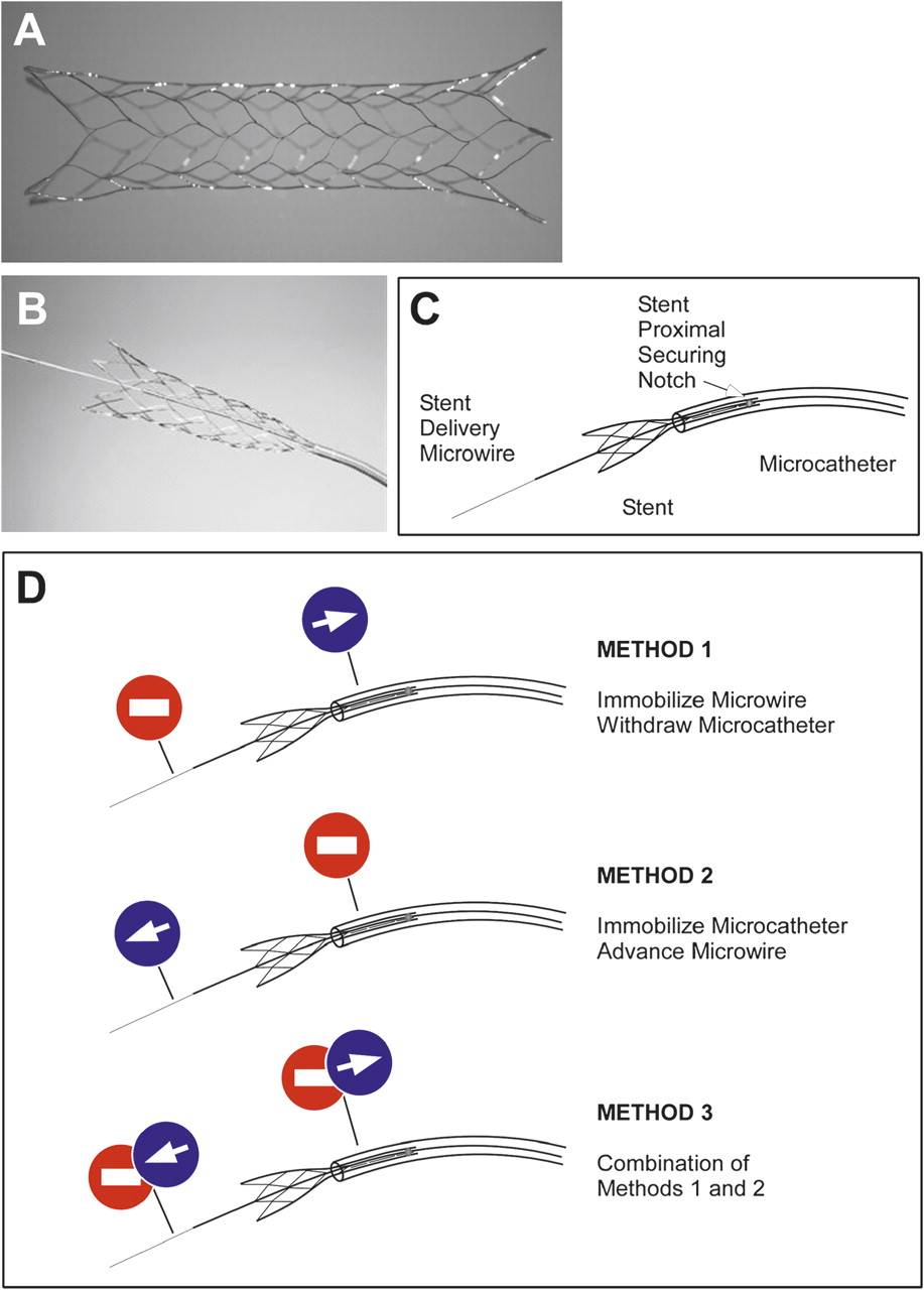
Enterprise (EN) vascular reconstruction device (A) is mounted on a delivery microwire (B, C). Illustration of the different delivery methods used to deploy the wire-mounted EN self-expanding stent (D).
Methods
Flow model and imaging
A silicone flow model connected to a flow pump was used under direct radiographic visualization in the angiography suite. The inner diameter of the tubing was 3.5 mm and the targeted curved segment had a radius of curvature of 7 mm (to center of lumen). A calibrated flat-panel biplanar Artis digital subtraction angiography system (Siemens, Malvern, Pennsylvania, USA) was used for all procedures. 3D FPCT was performed (DynaCT; Siemens) after the deployment procedure using all three deployment methods. Acquisitions were reconstructed and analyzed using the Leonardo software package (Siemens). The FPCT source images were visualized using multiplanar reconstruction and maximal intensity projection using Osirix software (64-bit version 3.8; Pixmeo, Bernex, Switzerland).
Deployment method
A standard Envoy 5-French guide catheter was used to advance a Prowler Plus Select 0.021-inch microcatheter (Codman Neurovascular, Chelmsford, Massachusetts, USA) across the targeted tubing bend over a 0.014 Agility microwire (Codman). A 4.5 mm×22 mm EN stent was advanced under fluoroscopic guidance and centered over the target aneurysm.The stent was then initially deployed using the same technique of immobilizing the delivery microwire and unsheathing the stent by withdrawal of the delivery (Prowler Plus Select) microcatheter until the flared ends and distal 5–6 mm of the stent were in contact with the wall (figure 1C). The rest of the deployment was then performed using three distinct methods (figure 1D). In method 1 (microcatheter pull-back), the stent delivery microwire was kept immobilized and the rest of the stent was unsheathed by simple withdrawal of the microcatheter (figure 1D, Top). Method 1 is recommended by the manufacturer in its instructions for use (‘If stent positioning is satisfactory, carefully retract the infusion catheter, while maintaining the position of the deliverywire, to allow the stent to deploy across the neck of the aneurysm. The stent will expand as it exits the infusion catheter.’). In method 2 (microwire push), the delivery microcatheter was immobilized and the stent delivery microwire was advanced to affect the remainder of the stent deployment (figure 1D, Center). In method 3 (balanced push–pull), a combination of methods 1 and 2 was used to insure that the tip of the delivery microcatheter remained centered in the middle of the lumen during the entire delivery process (figure 1D, Bottom).
Results
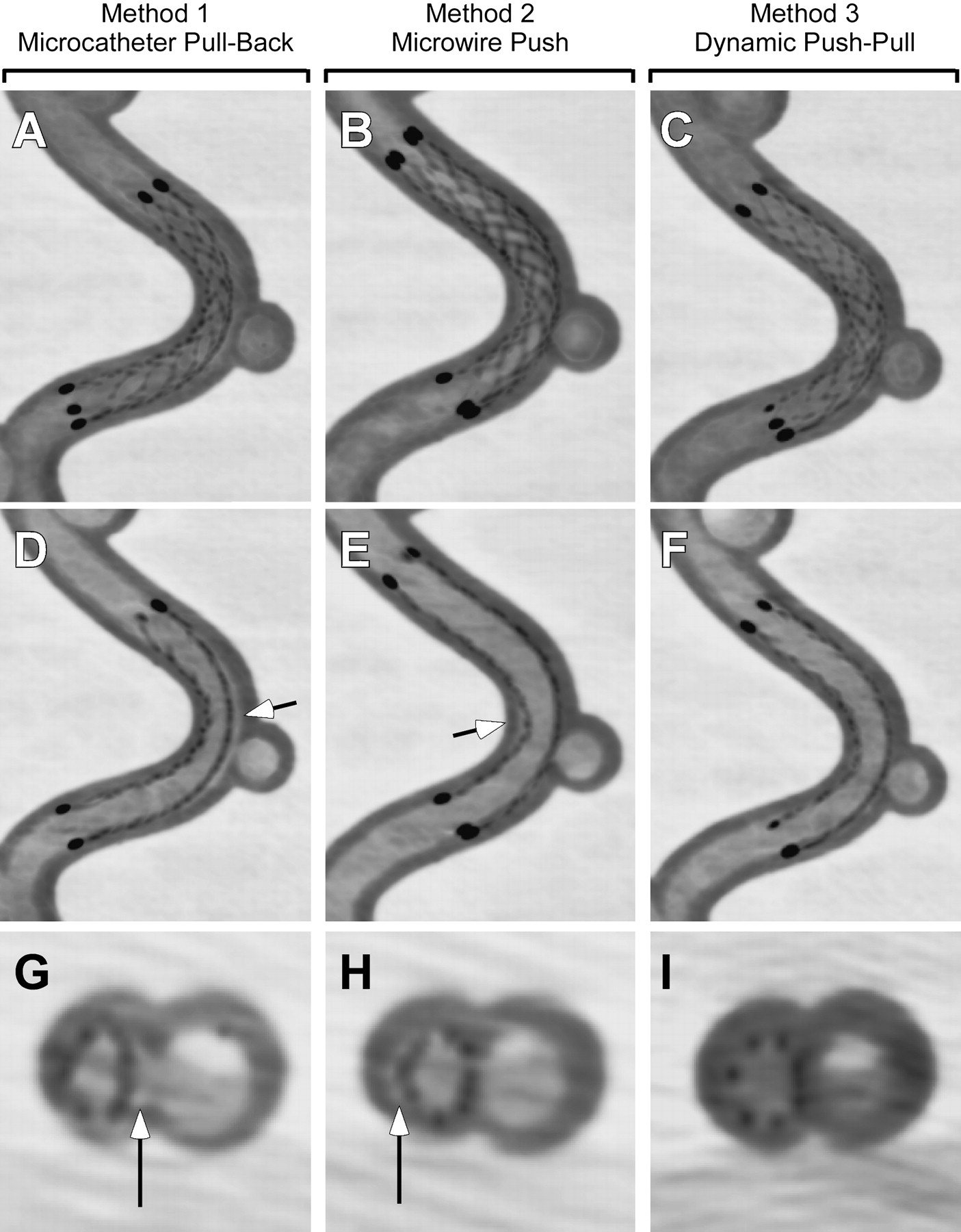
High-resolution FPCT imaging revealed a critical role for EN stent deployment technique in its apposition to the tubing wall on the curved test site (figure 2). Using the microcatheter pull-back technique (method 1), the EN stent tended to follow the contour of the inner vessel curve, with poor contact on the outer curve (figure 2A,D,G). This resulted in the development of significant outer curve ISA, seen as a crescent-shaped gap between the stent and the wall of the tubing. Conversely, using the microwire push technique (method 2) resulted in the EN stent following the outer contour of the curve during its deployment, with a consequent crimp on the inner curve and lack of apposition to the wall at that site (figure 2B,E,H), leading to inner curve ISA.

Sagittal thick (3.5 mm, A, B, C) and thin (1 mm, D, E, F) and axial thin (0.4 mm, G, H, I) reconstructions of high-resolution flat-panel CT in the same silicone model deployed using method 1 (microcatheter pull-back, A, D, G), method 2 (microwire push, B, E, H) and method 3 (dynamic push–pull, C, F, I). Note gap between the stent struts and inner wall (arrow).
By examining the tip of the delivery microcatheter during deployment with methods 1 and 2, it appeared that striving for a mid-luminal microcatheter position during the deployment process may alleviate or balance the tendencies of the stent to follow the outer or inner curve contours. Accordingly, the third technique of balanced push–pull is a combination of methods 1 and 2 that aims to mitigate both inner and outer curve ISA. This is achieved by careful monitoring of the microcatheter tip, applying microwire push when the tip is too close to the wall of the inner curve, and conversely pulling back on the delivery microcatheter when the tip is noted to be getting close to the outer curve. This dynamic balancing technique is continued until the entire stent is delivered, resulting in optimized inner and outer curve apposition (figure 2C,F,I).
Discussion
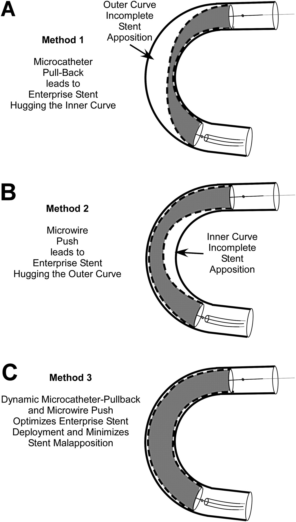
This report is the first to highlight the critical importance of deployment technique in the performance of the EN self-expanding stent. Despite using the same relatively large radius curvature silicone model, which is less tortuous than a typical carotid siphon, deployment technique resulted in significantly different configurations of the EN stent with the tubing wall leading to the appearance of outer, or inner curve stent–wall malapposition (figure 3).

Illustration of resulting incomplete stent apposition (ISA) patterns from deployment methods 1–3. Microcatheter pull-back (method 1) leads to the stent preferentially apposing the inner curve leading to outer curve ISA (A), while the microwire push (method 2) leads to the stent apposing the outer curve resulting in inner curve ISA (B). Method 3 (C) aims to minimize both patterns of malapposition.
The study has limitations as well, in that silicone tubing does not faithfully reproduce the frictional coefficient or the stiffness of a native vessel wall, even though it is likely superior to a rigid glass tubing model. In addition, a methodical analysis of the dependence of stent apposition on deployment technique at decreasing curvature radius or using different EN stent lengths was not performed in the current analysis.4 Because of it closed-cell design, it is possible that the EN stent may not be able to completely appose the vessel wall beyond a certain level of tight curvature, regardless of the deployment technique employed by the interventionalist. Rather, the purpose of the current study was to illustrate the phenomenon of deployment method dependence in a very mildly curved vessel, where the inherent closed-cell design property of the EN stent cannot be directly implicated as the only source of the finding.
There are a number of points of clinical relevance that can be derived from the findings described here. First of all, ISA has been shown to be related to short-term and long-term thromboembolic complications as well as vessel thrombosis and occlusion in the coronary circulation.7 These observations, however, were made in thicker-strut balloon-mounted coronary stents deployed in atherosclerotic vessels, and may not be applicable to the use of the thinner strut EN stent deployed in non-stenotic aneurysm-bearing vessels.
Second, a number of reports have implicated the EN stent in early and delayed migration.8 9 It is possible that lack of complete stent apposition to the wall may contribute to this phenomenon in two ways: (1) by decreasing the surface in contact with the vessel wall and making it more likely to migrate as a result of pulsation of the vessel wall (ratchet effect) or (2) by increasing the exposure of stent elements to the higher central flow velocities, which may increase the stent surface cross-section exposed to hemodynamic drag and lead to movement of the stent over time. The latter effect is unlikely to contribute to the reported proximal migration, however, because any hemodynamic drag would tend to move the stent downstream.
The third implication is related to subsequent navigation through the deployed stent under conventional fluoroscopy. It is feasible that an advancing microcatheter or microwire may inadvertently enter into the outer or inner region of ISA, which is not visible under standard fluorography used in neurointerventional procedures. This could thereby lead to entanglement between the microcatheter and the stent struts. The current study suggests the possible utility of FPCT imaging to evaluate the relative position of the advancing microwire or microcatheter with respect to the deployed EN stent and any areas of inner or outer curve ISA.
In conclusion, we have demonstrated that the method of deployment of the EN stent plays an important role in determining the way that the stent apposes to the wall and its configuration. This technical dependence should be kept in mind when deploying the device around curved and tortuous vessels in order to minimize the phenomenon of stent crimping, ovalization, incomplete stent apposition, and their potential deleterious clinical impacts.
Key messages
Advances in neurointerventional imaging, such as flat-panel CT, have enabled the visualization of the in vitro architecture of self-expanding intracranial stents.
Although crimping and ovalization of intracranial stents had previously been demonstrated with bending of already deployed devices, little is known of how the method of deployment may impact stent–vessel wall apposition.
This study reveals that deployment of the Enterprise intracranial stent in vitro using the microcatheter pull-back technique results in significant outer curve incomplete stent apposition (ISA), while the microwire push technique conversely leads to inner curve ISA.
Deployment using a dynamic push–pull technique aiming to keep the delivery microcatheter centered during deployment is noted to minimize both inner and outer curve ISA.
The manner in which the Enterprise stent is deployed can have a direct impact on its configuration vis-à-vis the vessel wall in curved segments.
Footnotes
Funding The senior author has received unrestricted research support from Boston Scientific and Codman Neurovascular.
Competing interests The senior author (AMM) has received unrestricted research support from Codman Neurovascular and Boston Scientific for unrelated research.
Provenance and peer review Not commissioned; externally peer reviewed.