Article Text

Abstract
Object The aim of this study is to demonstrate the differences between the new Low-profile Visualized Intraluminal Support (LVIS Blue) stenting device and the Flow Redirection Endoluminal Device (FRED) using a series of bench-top evaluations and optical coherence tomography (OCT) images in a cadaveric preparation of the basilar artery.
Methods The first part of the evaluation was bench-top microscopic documentation of metal coverage for LVIS Blue and FRED stents. OCT images of the cerebral vessels and deployed stents were acquired using OCT intravascular imaging. The stents were deployed from the left posterior cerebral artery to the basilar artery in a fresh frozen cadaver. Wall apposition and the relationship to jailed perforators were evaluated.
Results The metal coverage along the inner curves of the LVIS Blue stent was similar to that along the outer curves of the FRED stent. The LVIS Blue stent cell size was compatible for crossing with the tested microcatheters after deployment of the stent. The LVIS Blue stent showed better wall apposition and less coverage of the perforator than the FRED stent in the cadaver experiment.
Conclusions LVIS Blue has a good crossing profile for microcatheters, better wall apposition, and less perforator coverage than FRED. These are desirable features in territories with high densities of perforators such as the posterior circulation.
- Stent
- Aneurysm
This is an Open Access article distributed in accordance with the Creative Commons Attribution Non Commercial (CC BY-NC 4.0) license, which permits others to distribute, remix, adapt, build upon this work non-commercially, and license their derivative works on different terms, provided the original work is properly cited and the use is non-commercial. See: http://creativecommons.org/licenses/by-nc/4.0/
Statistics from Altmetric.com
Introduction
Endovascular treatment of complex intracranial aneurysms requires an extensive armamentarium of devices and new strategies. Certain types of cerebral aneurysms, particularly giant partially thrombosed and fusiform aneurysms, are considered to be the most challenging for treatment.1 ,2 Self-expandable intracranial stents have been increasingly used to treat these aneurysms. However, because of the low metal-to-artery ratio, the recurrence rate remains high. Flow diverters (FDs) have increased the rate of durable occlusion of wide-neck cerebral aneurysms. Holobasilar fusiform aneurysms are still a significant challenge due to the number of possible treatment complications and morbid natural history. The use of FDs on the posterior circulation has been associated with thromboembolic complications related to perforators.3 ,4
The development of a device to cover the gap between the first generation of self-expanding intracranial stents and FDs is very appealing. The Low-profile Visualized Intraluminal Support device Blue (LVIS Blue; MicroVention, Tustin, California, USA) is a braided stent and provides a higher degree of metal coverage (approximately 28%) than the first generation of self-expanding devices. The coverage of this stent is higher than that of the previous LVIS stent (approximately 23%) but lower than that of FDs (30–35%).5
We studied the performance of the new LVIS in different bench and cadaver models and compared it with that of a flow diverter Flow Redirection Endoluminal Device (FRED; MicroVention). We used a microscope in bench-top models and optical coherence tomography (OCT) imaging in the basilar artery (BA) of a human fresh frozen cadaver.
Methods
LVIS Blue
The LVIS Blue device is a self-expanding nickel titanium (nitinol), 16 single-wire braided, compliant, closed-cell design stent. This stent, which is compatible with a 0.021 inch microcatheter, has a cell size of 0.8 mm and is recommended for parent vessels with diameters of 2.5–4.5 mm. It has four radiopaque tantalum markers on the proximal/distal ends with two helical strands within the body of the stent. The LVIS device can be recaptured to up to approximately 75% deployment of its total length.
Flow Redirection Endoluminal Device (FRED)
The FRED stent is a self-expanding nickel titanium, single-wire braided, compliant, closed-cell paired-stent design composed of a low-porosity inner mesh of higher pore attenuation (48 nitinol wires) and an outer stent with high porosity (16 nitinol wires) designed mainly for the aneurysm neck. This stent, which is compatible with a 0.027 inch microcatheter, is recommended for a parent vessel size of 2.5–5.5 mm. It has four radiopaque markers on each end of the outer stent and two interwoven helical marker strands that attach the inner and outer stents, improving the visibility over its full length of dual-layer coverage. This FRED stent can be resheathed for up to 50% deployment of its total length.
Bench-top experiment
Bench-top experiments were performed to evaluate changes of neck coverage surface area (%). We made a fusiform aneurysm using clear silicone tubes slit down the middle, with an inner diameter of 3 mm. The LVIS Blue stent (3.5×22 mm and 4.5×23 mm) and FRED stent (3.5×22 mm and 4.0×22 mm) were deployed twice between the proximal and distal silicone tube, which was empty in the middle portion. These models were fixed in a straight and 180° curved fashion and photographed under a microscope.
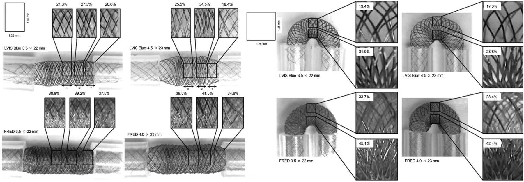
The neck coverage surface areas are shown in figure 1. The mean neck coverage surface area (%) was calculated as [1−(Z×L)/(X×Y)]×100, where X and Y are each side of an imaginary rectangle on the stent, Z is the width of the struts, and L is the length of total struts in the rectangle. L was calculated as follows: L (mm)=total length of struts−Z2×N, where N is the number of intersections by the two struts. In the straight model, we measured surface coverage at the center. The three types of metal coverage were measured in the straight model because three different zones were found in the square on the stent in figure 1 left. The three zones were defined as the middle of the aneurysm neck (mid-zone), the transition between the parent artery and the neck (transition zone), and the zone between the mid-zone and the transition zone (high-density zone). Both meshes in the FRED stent were calculated. In the straight model, the lengths X and Y were 1.20 mm and 1.85 mm, respectively. In the curved model, the outside and inside areas in the center of the curvature were measured. The lengths X and Y were each 1.25 mm.

Photographs by microscope showing straight (left) and 180° curved models (right) of a fusiform aneurysm in a 3 mm diameter vessel in which the new Low-profile Visualized Intraluminal Support device (LVIS Blue) (3.5 mm and 4.5 mm) and the Flow Redirection Endoluminal Device (FRED) (3.5 mm and 4.0 mm) were deployed. Left: the neck coverages for each stent in the three zones (mid-zone; M: high-density zone; H: Transition zone; T) are shown in a straight model. Right: the neck coverages for each stent in the outer and inner curves are shown in a 180° curved model.
To prove the feasibility for additional coil insertion after deployment of the device, we evaluated the possibility of stent cell penetration for the devices in the 180° curved model using Echelon-10, Marathon (ev3, Plymouth, Minnesota, USA), and Headway Duo microcatheters (MicroVention).
OCT imaging in the fresh frozen cadaver
This study was performed with a fresh frozen human cadaver. Brain and intracranial vessels were removed from the human cadaver. A 6 and 5 French short sheath were inserted via the left and right vertebral arteries (VAs) and fixed, respectively. OCT images were obtained after the Dragonfly Optis intravascular Imaging Catheter (Lightlab Imaging, St Jude Medical, St Paul, Minnesota, USA) was advanced into the left posterior cerebral artery (PCA) through the sheath in the left VA along a microwire monorail system. The LVIS Blue stent (4.5×32 mm) and FRED stent (4.0×32 mm) were selected because the diameter of the BA was 3.57 mm. The LVIS Blue stent was deployed twice from the left PCA to the BA. OCT images were obtained after deployment of the stent. The same procedure was performed for the FRED stent after the LVIS Blue stent was removed. To obtain clear images, residual cadaveric blood products were flushed with contrast injection through the sheath in the right VA. Offline OCT analysis was performed with Lightlab Imaging software.
Results
The mean metal coverages of LVIS Blue and FRED are shown in figure 1. The metal coverages of the LVIS Blue stent in the mid-zone, high-density zone and transition zone were 21.3%, 27.3% and 20.6%, respectively. The effect of oversizing additionally led to a change in the metal coverages (4.2%, 7.2% and −2.2%). On the other hand, no difference in the metal coverages of the FRED stent was seen among the positions (38.8%, 39.2% and 37.5%). Furthermore, there was hardly any difference in metal coverages for the oversized stent (39.5%, 41.5% and 34.6%). The neck coverage for the high-density zone in the 4.5 mm LVIS Blue stent was comparable to that of the FRED stent. In addition, the inner neck coverage of the LVIS Blue stent was similar to the outer neck coverage of the FRED stent in the 180° curved model.
A trans-cell approach after deployment of the stent was performed using Echelon-10, Marathon and Headway Duo microcatheters. The trans-cell approach was shown to be feasible after deployment of the LVIS Blue stent (figure 2). It was impossible to penetrate the stent strut of FRED. This result was consistent with the result of the smaller cell size in the FRED stent than the LVIS Blue stent (figure 1).

Photographs showing the possibility of protrusion through the stent strut using three types of microcatheter. The Flow Redirection Endoluminal Device (FRED) shows the impossibility of protrusion. The white circles show the tips of the microcatheters.
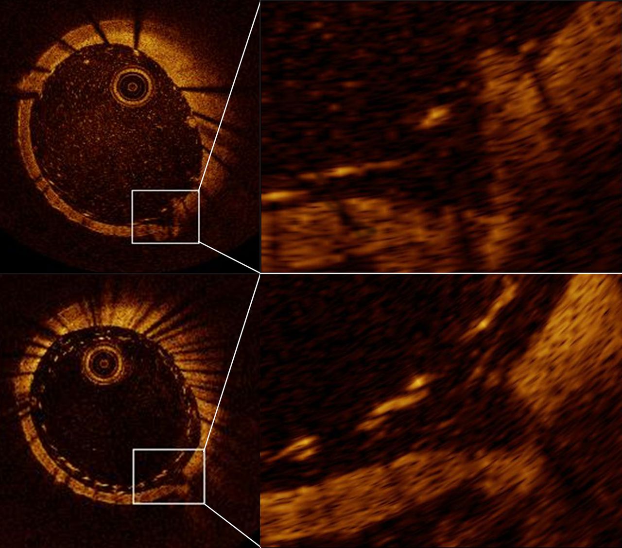
Figure 3 shows OCT images after each deployment of the LVIS Blue 4.5 mm stent (upper) and the FRED 4.0 mm stent (lower) in the BA, which had a mean diameter of 3.57 mm. The distance between the orifice of the perforator and the stent strut was 0.10 mm with the LVIS Blue stent and 0.21 mm with the FRED stent. In whole vessel image, the LVIS Blue stent showed better wall apposition than the FRED stent. The orifice of the perforator was covered by one stent strut with the LVIS Blue stent compared to two with the FRED stent.
Photographs showing optical coherence tomography (OCT) images after deployment of the new Low-profile Visualized Intraluminal Support device (LVIS Blue) (top) and the Flow Redirection Endoluminal Device (FRED) (bottom) in the same vessel. Defects of the vessel wall indicated by white squares show a perforator. The orifice of the perforator and the stent strut are seen in the magnified views. The LVIS Blue stent demonstrates better wall apposition and less perforator coverage than the FRED stent.
Discussion
The most important finding in this study is that the LVIS Blue stent demonstrated feasibility for the trans-cell approach and better wall apposition and less perforator coverage than the FRED stent. In addition, this stent showed that inner metal coverage in the curved model was comparable to metal coverage of FDs. Therefore, this study suggests the possibility that this stent has an advantage over FDs and previous intracranial stents.
The new LVIS Blue stent has a smaller angle between the wires of the mesh. This modification resulted in better wall apposition and denser mesh compared with the first-generation LVIS. The braided morphology showed better conformability, apposition to the vessel wall, and stability.6 This design allowed the LVIS Blue stent to be delivered through lower profile microcatheters (0.021 inch) than the FRED stent (0.027 inch). The lower profile means that it is easier to deploy the stent into more distal vessels and to use an adjunctive method. In addition, as the cell size of the braided stent is more easily changed than with other stents, the LVIS Blue stent allows crossing with microcatheters through the stent cells to place coils in aneurysms (figure 2). On the other hand, it is impossible to penetrate the stent strut of the FRED device because of the small cell size. After recanalization of an aneurysm treated with the LVIS Blue stent is recognized, retreatment by a trans-cell approach is possible.
The neck coverage of FDs was reported to be 30–35%.5 The porosity of the stent induces the possibility of flow stasis in the aneurysm due to rapid thrombosis.7 Generally, pore number can play an important role in thrombosis. Our results showed that the FRED stent had a high pore density while the LVIS Blue stent had a much lower pore density. Furthermore, FDs may provide scaffolding for endothelialization and vessel wall healing. For these reasons, FDs demonstrate a higher occlusion rate for intracranial aneurysms than most stents. On the other hand, the neck coverage for an intracranial stent was reported to be 10% in Neuroform and 9% in Enterprise.8 The main purpose of the intracranial stent is to keep coils in the aneurysm, and especially to insert finishing coils so that a higher occlusion rate can be achieved. Additionally, these intracranial stents are feasible for retreatment via a trans-cell approach because of low neck coverage. In our results, the LVIS Blue stent showed higher neck coverage than previous intracranial stents. The inner neck coverage with the LVIS Blue stent in the curved model was comparable to 30–35% of FDs reported previously (figure 1, right).5 A high aneurysm occlusion rate, similar to that of FDs, might be particularly expected for an aneurysm in the inner curve of a vessel. However, we should take into consideration the impossibility of the trans-cell approach and the concern for the ischemic complications of a perforator originating from the inner curve.
In the case of an oversized LVIS Blue stent, the transition zone showed lower neck coverage than the proper-sized stent in figure 1, left (18.4% vs 20.6%). On the other hand, a greater neck coverage rate was shown in the high-density zone of a 4.5 mm LVIS Blue stent than a 3.5 mm stent (34.5% vs 27.3%). Shapiro et al9 reported that the funnel-shaped transitional zone in the Pipeline Embolization device (PED; Medtronic) was dependent on the degree of mismatch between the device diameter and the diameter of the recipient artery. In addition, they also reported that PEDs deployed in larger tube diameters than the nominal device diameter showed more metal coverage. Taking this into account, these results are consistent with our results that metal coverage in the transition zone of the 4.5 mm LVIS Blue stent is less than the 3.5 mm LVIS Blue stent but is more in the mid-zone and high-density zone. In the straight model, the neck coverage of the 4.5 mm LVIS Blue stent was comparable to FDs in the high-density zone. As the high-density zone is consistent with the outflow of an aneurysm, this result might induce more flow stasis so that the LVIS Blue stent could show a higher aneurysm occlusion rate. Meanwhile, these results suggest that the stent strut in the 4.5 mm stent was more compressed in the high-density zone such that stent migration may occur if the landing zone is short. Although the difference in neck coverage between the 3.5 mm and 4.0 mm FRED stent was smaller, the same tendency was shown. These observations are in excellent agreement with the results published by Shapiro et al.5 ,9
In our OCT experiment, the LVIS Blue stent showed better wall apposition than the FRED stent (figure 3). In addition, the LVIS Blue stent expanded further outward than the FRED stent (figure 1). These results confirm that the LVIS Blue stent had greater apposition to the vessel wall, as described above. In previous reports, insufficient opening of the FD was reported to occur in up to 10% of cases.10–12 Additionally, Heller et al13 reported that incomplete stent apposition of the Enterprise stent was associated with periprocedural ipsilateral thromboembolic complications. Moreover, in 5 of 29 patients (17%), in-stent percutaneous transluminal angioplasty (PTA) was required because the risk of thrombus formation and subsequent parent artery occlusion is high if wall apposition is not adequate.3 ,14 ,15 Use of the LVIS Blue stent might reduce the thromboembolic complications due to malposition and complications related to PTA.
There are some reports on perforator infarction after deployment of FDs. One of 29 patients showed delayed perforator stroke by diffusion-weighted imaging despite sufficiently effective antiplatelet therapy according to platelet function tests.3 Phillips et al4 reported that the permanent neurologic complication rate was 9.4%; in particular, perforator territory infarctions occurred in 14% of patients with BA aneurysms. Brinjikji et al16 reported that perforator infarction was 3%, but significantly higher odds were found among patients with posterior circulation aneurysms. Additionally, Kallmes et al17 reported that ischemic stroke rates were 4.7%, and even higher in patients with posterior circulation aneurysms (7.3%). The treatment for a fusiform aneurysm in the posterior circulation is still challenging because there are many perforators in the BA. In our OCT experiment, the LVIS Blue stent showed less perforator coverage than the FRED stent (figure 3). This result suggests that the LVIS Blue stent could reduce ischemic complications related to perforators.
As a result, better wall apposition and less perforator coverage in the LVIS Blue stent might reduce ischemic complications. In addition, neck coverage comparable to FDs might induce a higher rate of aneurysmal occlusion than previous intracranial stents. It is possible that this stent offers a ray of hope for fusiform aneurysms in the posterior circulation and may be a treatment option in the near future. A clinical trial is needed to prove its feasibility in the treatment of posterior fusiform aneurysms.
This main limitation is that this is not an in vivo experiment, so clinical practice might show different results. In the curved model we focused the line of sight of the camera around the center of the stent, which might be less accurate about the surface coverage of the outer and inner curve (figure 1). Determining perforator coverage in the OCT experiment is challenging as the two devices have different wire diameters. Counting the number of struts near the perforator orifice could provide very limited information for comparing perforator occlusion. In addition, there is no statistical comparison in this paper. More models and devices should be examined by way of comparison.
Conclusions
Retreatment after deployment of the LVIS Blue stent was possible via the trans-cell approach. The LVIS Blue stent demonstrated the possibility of better wall apposition and less perforator coverage than the FRED stent in our cadaver experiment. In particular, the inner metal coverage in the curved model was comparable to metal coverage of FDs. The LVIS Blue stent is expected to show a higher aneurysm occlusion rate than an intracranial stent and fewer perforator-related ischemic complications than FDs. This stent might be a good option for the treatment of fusiform aneurysms in the posterior circulation. Clinical studies using this stent are needed.
Acknowledgments
The authors thanks St Jude Medical for lending the Lightlab Imaging catheters and analysis system used in the study, and specifically Paul Sahagian's assistance in troubleshooting the OCT system and creating the pictures. The authors thank the Rush University anatomy laboratory for assistance with cadaver care.
References
Footnotes
Contributors DKL conceived the study. YM and JC executed the study. All authors reviewed the final version of the submitted manuscript.
Competing interests None.
Provenance and peer review Not commissioned; externally peer reviewed.