Article Text

Abstract
The aim of this review is to describe the acquisition and reformatting of state of the art high resolution cone beam CT (HR-CBCT) and demonstrate its role in multiple neurovascular conditions as a tool to improve the understanding of disease and guide therapeutic decisions. First, we will review the basic principle of CBCT acquisition, followed by the injection protocols and the reformatting paradigms. Next, multiple applications in different pathological conditions such as aneurysms, arteriovenous malformations, dural arteriovenous fistulas, and stroke will be described. HR-CBCT angiography, widely available, is uniquely useful in certain clinical scenarios to improve the understanding of disease and guide therapeutic decisions. It rapidly is becoming an essential tool for the contemporary neurointerventionalist.AChoAho
- Aneurysm
- Angiography
- Flow Diverter
- Technology
- Vascular Malformation
Statistics from Altmetric.com
Introduction
Clear understanding of the complex angioarchitecture and vasculature in relation to intracranial bony structures is essential in endovascular clinical decision-making. Two-dimensional digital subtraction angiography (2D-DSA) is the standard imaging technique for the evaluation of cerebrovascular conditions, and has been the mainstay of diagnostic cerebral angiography since its inception. Since the introduction of rotational DSA with three-dimensional (3D) reconstruction in the late 1990s,1 it was quickly recognized as giving paramount additional information for the evaluation of neurovascular lesions,2 leading to its routine adoption.3 Multiple subsequent variations were developed, including 3D-3D fusion,4 4D DSA,5 and arterial and venous (AV)-3D-DSA.6
All volumetric datasets acquired by modern angiographic machines are based on the cone beam CT (CBCT) technique. While commercial and marketing considerations produce various proprietary names, reflecting the suggested purpose of a particular algorithm (DynaCT, 3D-DSA, VasoCT, Innova CT), all rely on the same underlying image acquisition principles.3 7–9
The aim of this review is to describe the principles, acquisition and reformatting of state of the art high resolution CBCT (HR-CBCT) angiography and demonstrate its role in multiple neurovascular conditions as a tool to improve the understanding of the angio-architecture of disease and guide therapeutic decisions.
Image acquisition
The basic principle of CBCT is the acquisition of multiple X-ray projections during gantry rotation around a volume of interest, usually spanning a total of 200°.7 The resulting series of images is back-projected to produce a volumetric dataset.8 9 Newer machines, destined to soon become the standard, use acquisition obtained with alternative techniques compared with the traditional circular one, named sine spin10 or dual-axis butterfly11
Manufacturers offer different CBCT acquisition protocols that are targeted and optimized for certain clinical tasks. The acquisition protocols can differ in several basic parameters such as beam kVp, focal spot size, maximum X-ray pulse length, number of frames acquired per degree of rotation, dose per frame, number of pixels acting as detection unit, field of view (FOV), and presence of a ‘mask’ or background image. Various differences also exist in both reconstruction and reformatting of the acquired dataset.
In our institution we use Siemens Artis Q (Siemens, Erlangen, Germany) technology with the following types of CBCT acquisitions relevant to neurointerventions: 3D-DSA for subtracted visualization of contrast enhanced vessels, ideal for ‘workhorse’ applications such as selection of appropriate projections for aneurysm treatment, and DynaCT (VasoCT for Philips, Innova CT for GE), to which we refer in this paper as HR-CBCT to distinguish it from the above described 3D-DSA. It is again emphasized that both are based on the same acquisition principles, and differ only in various trade-offs, such as speed of acquisition, resolution, radiation dose, etc.
The 3D-DSA acquisition achieves comparatively low soft tissue resolution due to the relatively low number of projection images (n=133), resulting in more stripe artifacts, and a low detector dose level, contributing to a relatively low signal-to-noise ratio. Advantages of the technique, however, include faster acquisition, allowing for better arteriovenous phase separation and lower X-ray exposure.
DynaCT differs from the 3D-DSA acquisition mode, resulting in higher resolution, due to the significantly higher number of projection images (n=500) acquired, and the higher detector dose used, both factors contributing to a much better resolution, at the expense of longer acquisition times and higher radiation exposures.
Vendors generally provide two HR-CBCT (DynaCT) protocols, a low and a high kV option. CBCT protocols targeted to visualize iodinated contrast media have their kVp set to lower values, typically 70 kV, closer to the k-edge of iodine (33 keV) to maximize x-ray absorption. For more challenging CT scenarios, such as the detection of soft tissue or hemorrhage adjacent to the skull without the application of contrast media, a higher kVp (109 for Siemens) is advantageous as this reduces the beam hardening artifacts at the skull. The higher kVp HR-CBCT protocol is also best suited for imaging high density structures such as metallic implants or bone. In practice, however, many factors seem to contribute to the final appearance of the image, with 109 kVp acquisitions appearing to often yield superior results in terms of image quality compared with 70 kVp for all HR-CBCT applications in our experience.
Detector readout bandwidth limitations sometimes make it necessary to combine detector pixels (making 4 pixels act as 1) to keep the acquisition times within an acceptable range. This comes at the expense of spatial resolution. Alternatively, to maximize the spatial resolution, a small (22 cm typically) detector area can be used, which activates the acquisition in a non-binned mode (called DynaCT Micro in Siemens), as opposed to the 2×2 pixel binning (combining pixels) typically used for acquisitions with a larger FOV.12 The caveat of using a higher magnification is that the proceduralist must more carefully set up the acquisition to ascertain the inclusion of the area of interest in the middle of the FOV.
Injection protocols
The typical protocols are to inject full contrast for arterial vessel imaging (such as 3D-DSA) and dilute contrast (20–30% contrast in saline) for post-implant evaluation. However, longer full contrast injections such as during DynaCT can be extremely useful for dramatically enhancing the resolution of vascular imaging.
It is our experience that an ad hoc approach works best when selecting optimal injection protocols. A few factors need to be taken into consideration when deciding what flow rate/volume/injection delay protocols are optimal. The aim is to have full opacification of the target vessel throughout the entire acquisition without any remarkable inflow of non-opacified blood.
Factors to consider are: (1) the size of the vessel in which the injection catheter is located; (2) the distance between the target anatomy and the catheter location; and (3) the acquisition protocol chosen. These factors will imply what flow rate/volume/delay injection rate should be used. For example, in a typical situation where the catheter is located in a nominally adult-sized distal cervical internal carotid artery (ICA), and the aim is to characterize the intracranial ICA using a 20 s acquisition CBCT, a flow rate of 3 mL/s is usually sufficient to obtain full vessel opacification. Given the distal cervical location of the catheter and assuming a normal heart rate and cardiac output, 1–1.5 s delay from the start of the injection to the beginning of image acquisition typically is enough to visualize the ICA territory in its entirety. The delay chosen can be more carefully refined using 2D-DSA imaging previously obtained as part of routine angiography. Since a 20 s acquisition protocol is chosen, one needs to make sure that the vessel of interest is opacified throughout the entire acquisition. This duration requirement will drive the calculation of the contrast volume to inject, which for this particular case, equates to a volume of 3×21=63 mL of undiluted contrast. In terms of pressure, our standard is 300 PSI (pounds per square inch) but that can be adjusted based on the catheter used and the catheter location.
A specific situation arises in the case of HR-CBCT angiography obtained through a microcatheter injection, usually during cranial or spinal vascular malformation or during tumor embolization procedures. In these cases the PSI rating of the microcatheter must be accurately confirmed to verify the safety of the injection, and we usually use a flow rate of 0.6 mL/s (with a volume of 12 mL for a 20 s CBCT). Alternatively, sometimes injections are done by manual injection with appropriate shielding of the operator.
Reformatting paradigm: small volume of interest, maximum intensity projection, and volume rendering
The final image quality is dependent not only on the acquisition protocol, but on the manner in which the source images are reformatted.
The reconstruction and data processing/display protocols vary and are highly proprietary. Standard options include volume rendering and maximum intensity projections (MIPs) for volumetric images, and MIP/averaged projections for cross-sectional datasets.
While large FOV acquisition and large volume of interest (VOI) reconstruction can generate beautiful and detailed images, it is by reducing both that the potentials of CBCT are fully realized. Indeed, while a 48 cm FOV with a full VOI generates a volume with a voxel size of 0.5 mm, use of a smaller 22 cm FOV coupled with a small VOI reconstruction is capable of generating images with a voxel size up to 0.02 mm. Such small VOI reconstructions are essential for the accurate detailed study of small branches such as small perforators, retinal branches, spinal arteries and so forth, as will be demonstrated below with practical scenarios. For the reconstruction of the volumetric data as axial images a Hounsfield unit (HU) versus edge enhancement (EE) kernel and a reconstruction image characteristic (normal, sharp or smooth) can be chosen. It is our experience that the best algorithm varies patient by patient rather than being the same for the corresponding structures, possibly in relationship to heterogeneities introduced by additional factors, such as skull thickness, or patient motion artifact—best curbed by use of apnea during general anesthesia—throughout image acquisition. Once the volume is reconstructed, it can be visualized using MIP or multiplanar reformatting (MPR) techniques; please refer to traditional radiology literature for better understanding of the different roles of these techniques. In our experience the MIP slab provides superior rendering of the vasculature with its inherent capability of having the whole maximally opacified vascular structure highlighted in a single image. The thickness of the MIP image must be finely tuned based on the vessel of interest and vessel location in order to include the whole vessel in the image—the thicker the better—trying to avoid other irrelevant structures such as other vessels or bone. Regardless of the reformatting method, MIP or MPR, a volume rendered image may be generated from the selected VOI and rotated as desired according to the interpretation needed. Notably, the volume rendering reformats obtained with HR-CBCT can be overlayed in real-time to the 2D images in the same way that the 3D-DSA reformats are traditionally used, enabling appropriate views to be selected during the procedure.
Application in disease
HR-CBCT angiography has proven useful in understanding vascular anatomy due to several factors. First and foremost, the inherent 3D capability makes it possible to visualize the curvilinear vascular structures through 3D space along any plane warranted; the visualization of bone, including its canals and foramina, allows a very detailed analysis of a vessel’s course, something difficult with the traditional 2D-DSA.HR-CBCT also has higher resolution compared to the more commonly used 3D-DSA. With appropriate acquisition protocols and reformatting algorithms, HR-CBCT provides explicit insight into the most detailed anatomy, showing, in effect, essentially the level of resolution available to the neurosurgeon under the operating microscope.
We will demonstrate in the following paragraphs the capability of HR-CBCT acquired during angiography to aid the neurointerventionalist in different pathological conditions. All the images were acquired during routine clinical care as per neurointerventionalist preference.
Aneurysms
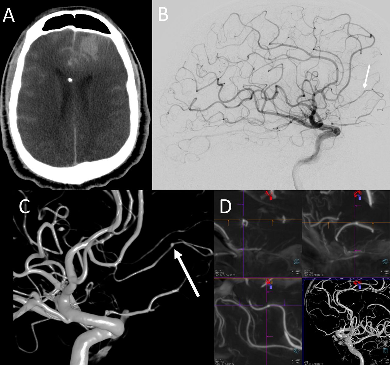
Apart from its common use for post-implant evaluation after aneurysm treatment13 (figure 1), which can also be done non-invasively with intravenous contrast injection,14 HR-CBCT has found utility in several aspects of pre-treatment evaluation and planning—for example, in the identification of very small aneurysms, particularly in the posterior circulation. The limited sensitivity of 2D DSA in patients with perimesencephalic hemorrhage is well known and it is our experience that HR-CBCT provides a significant and critically important increase in resolution enabling detection of very small aneurysms (figure 2). We recommend HR-CBCT acquisition when there is a particularly high suspicion for aneurysm and the images acquired with the traditional 2D- or 3D-DSA are not definitively answering the clinical question. Similarly, HR-CBCT has been found useful in identifying traumatic (figure 3) or mycotic (figure 4) aneurysms when the 2D-DSA failed in obviously pointing to the disease. Another role of HR-CBCT in the work-up of brain aneurysms is to evaluate the detailed features of a target aneurysm before treatment, such as: small lobulations in the aneurysm fundus, better understanding of complex neck aneurysms (figure 5), or, as importantly, the presence of small perforators arising from the aneurysm itself (figure 6) or from the parent vessel close to the aneurysm neck—specifically of paramount importance in cases of parent vessel sacrifice such as in dissecting vertebral artery aneurysms (figure 7).15 16
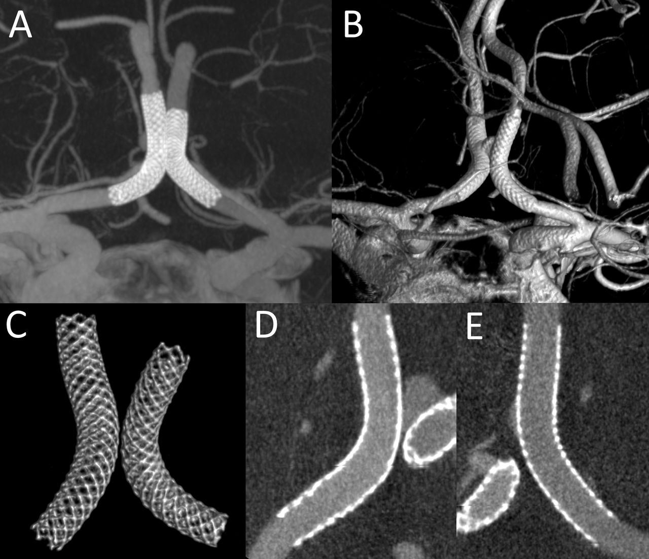
Post bilateral Pipeline embolization (H-Pipe) technique for the treatment of an ACom aneurysm. Images obtained with HR-CBCT 20 s (DynaCT) 109 kV, with bilateral ICA arterial catheter injections. Thick MIP reformat (A) showing the two kissing devices and good flow in both ACAs. The same can be visualized with the volume rendering technique (B). If the image is appropriately windowed and cropped, a selective visualization of the stents only can be obtained which demonstrates in high resolution the details of the devices (C). Finally, by looking at thin MIP curved reformats, a good apposition for both stents (D, E) can be confirmed. ACAs, anterior cerebral arteries; ACom, anterior communicating artery; HR-CBCT, high resolution cone beam CT; ICA, internal carotid artery; MIP, maximum intensity projection

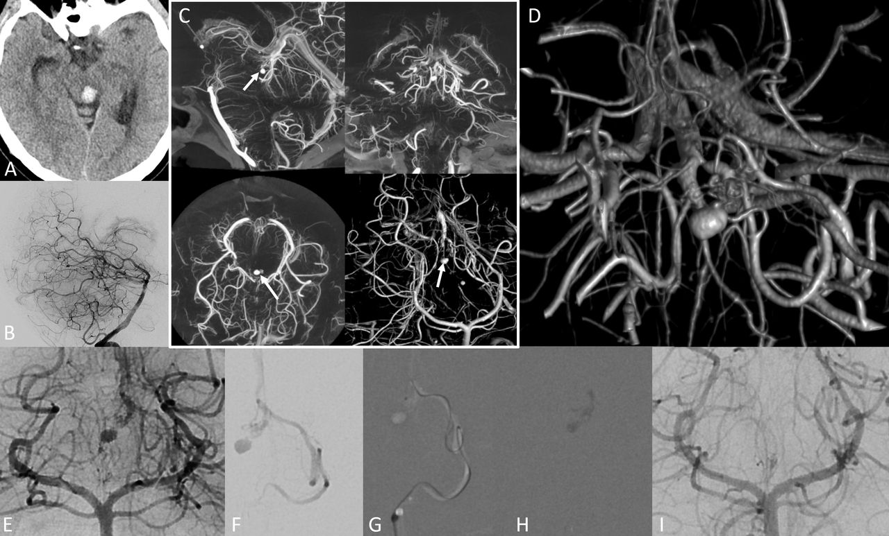
Adult man presenting with subarachnoid hemorrhage (A). 2D-DSA in frontal (B) and lateral (C) projections did not show any finding concerning for ruptured aneurysm. HR-CBCT angiography with volume rendered reformats (D, E) clearly showed a basilar perforator aneurysm (arrows), originating separately from the superior cerebellar artery. 2D-DSA, two-dimensional digital subtraction angiography; HR-CBCT, high resolution cone beam CT.

Adult man presenting with altered mental status post trauma. Head CT (A) showed diffuse subarachnoid hemorrhage and left frontal intraparenchymal hemorrhage. 2D-DSA showed oligemia in the region of the left frontal hematoma (B). Only after performing HR-CBCT angiography with volume rendered (C) and multiplanar MIP reformats (D), a traumatic pseudoaneurysm was identified (arrow in C) and subsequently treated with coil sacrifice of that branch. Retrospectively, the aneurysm was visible on the 2D-DSA image (B) but only after its identification on the HR-CBCT images. 2D-DSA, two-dimensional digital subtraction angiography; HR-CBCT, high resolution cone beam CT; MIP, maximum intensity projection.

Adult man presenting with headache and clinical question of endocarditis with head CT showing a small parietal convexity subarachnoid hemorrhage (A) raising the question of mycotic aneurysm. 2D-DSA of right ICA in lateral projection (B) did not show an aneurysm. HR-CBCT reconstructions (C), using both the thick MIP and the volume rendering with small VOI centered in the parietal area, proved the existence of a small fusiform aneurysm of the central branch of the right MCA. Based on the geometry provided by the HR-CBCT, appropriate DSA projection was then acquired (D) now confirming the mycotic aneurysm identified on the reconstructed images. 2D-DSA, two-dimensional digital subtraction angiography; HR-CBCT, high resolution cone beam CT; ICA, internal carotid artery; MCA, middle cerebral artery; MIP, maximum intensity projection; VOI, volume of interest.

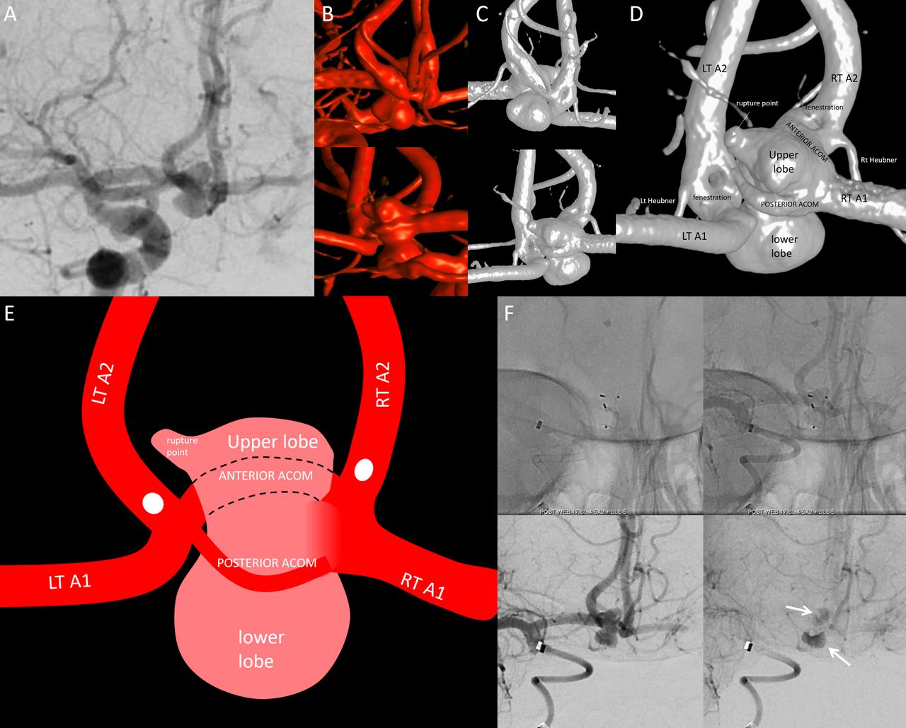
Young woman presenting with subarachnoid hemorrhage due to a flow-related ACom aneurysm in the setting of left ICA chronic occlusion. 2D-DSA frontal view of right ICA injection (A) shows the ACom aneurysm with superior and inferior projecting lobulations. 3D-DSA acquisition with 6 s CBCT in anterior and posterior projections (B) failed to demonstrate enough details of the aneurysm in order to understand its complex features and find a treatment strategy. In order to improve the understanding, an HR-CBCT (20 s 109 kV DynaCT with arterial injection) was performed (C, in same anterior and posterior projections as 3D-DSA), now showing details of aneurysm anatomy with the double ACom and two additional fenestrations with the aneurysm extending above and below in between the two limbs of the fenestrations (magnified in D and schematized in E). Based on a fuller understanding of the anatomy, treatment with two stacked WEB devices was successfully undertaken, with excellent intra-aneurysmal stasis (arrows) and preserved ACom flow at the end of the procedure (F). ACom, anterior communicating artery; CBCT, cone beam CT; 2D-DSA, two-dimensional digital subtraction angiography; 3D-DSA, three-dimensional digital subtraction angiography; HR-CBCT, high resolution cone beam CT; ICA, internal carotid artery; WEB, Woven EndoBridge.

Young woman with ruptured anterior choroidal artery aneurysm. Traditional 3D-DSA (A) and HR-CBCT (B) were performed, showing the AChoA aneurysm and the PCom infundibulum. The HR-CBCT was then reconstructed with a smaller VOI to improve the spatial resolution (C). From the images obtained with this smaller VOI, the aneurysm details could be better assessed. Two perforators, one from the aneurysm neck (dashed arrows) and one from the dome (solid white arrows), and several dome daughter aneurysm sacs (black arrows) are well-seen (D, E). The aneurysm was coiled, with pre-coil (F) and post-coil (G) DSA images demonstrating loss of the dome-origin perforator (white arrows), with a corresponding small acute infarct on subsequent diffusion MRI (arrow, H). These images demonstrate how HR-CBCT images, especially when reconstructed in a small VOI, are able to show details that cannot otherwise be identified on the more traditional 3D-DSA and hard to understand on the 2D-DSA. ACom, anterior communicating artery; 2D-DSA, two-dimensional digital subtraction angiography; 3D-DSA, three-dimensional digital subtraction angiography; HR-CBCT, high resolution cone beam CT; PCom, posterior communicating artery; VOI, volume of interest.

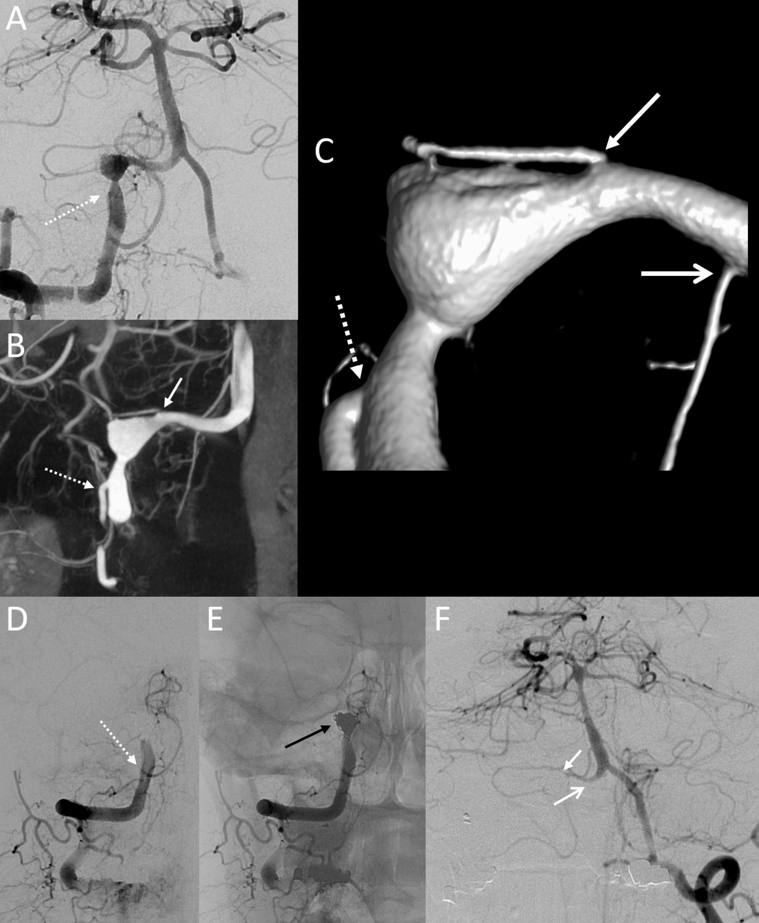
Young man with subarachnoid hemorrhage related to a dissecting intradural vertebral artery aneurysm (2D-DSA frontal view in A), amenable to sacrifice given the well-sized contralateral vertebral artery. HR-CBCT reformatted in coronal thick MIP (B), then reconstructed in smaller VOI to visualize more details (C), showed the branches originating close to the aneurysm, specifically, other than the obvious PICA (dotted arrow in A, B, C), also an additional cortical PICA branch (white arrow in B, C) and the ASA (open arrow in C). Given the information learned from the reformatted HR-CBCT images, a more focal sacrifice strategy was performed with attention to spare the described branches. While the PICA, and maybe the ASA, could have been identified with conventional 2D-DSA and 3D-DSA imaging, the additional PICA branch would have been extremely hard to prospectively identify and spare without HR-CBCT. Post-treatment DSA (D–F) in frontal projection showing the preserved flow in the PICA (dotted arrow in D), the coil mass in the aneurysm (black arrow in E) and the preserved flow to the vertebrobasilar system from the left vertebral artery, with preserved flow in the right sided cortical PICA branch and ASA (arrows in F). ASA, anterior spinal artery; 2D-DSA, two-dimensional digital subtraction angiography; 3D-DSA, three-dimensional digital subtraction angiography; HR-CBCT, high resolution cone beam CT; MIP, maximum intensity projection; PICA, posterior inferior cerebellar artery; VOI, volume of interest.
Brain arteriovenous malformations
In brain arteriovenous malformations (AVMs), HR-CBCT has been used for localization purposes, either for surgical17or stereotactic radiation18 planning. In our practice it has also found a role for enhanced understanding of the vascular microanatomy of an AVM. Generally speaking, this is not a common scenario, since most of the information is usually gathered with 2D-, 3D- or 4D-DSA imaging. But the images provided by HR-CBCT do contain more data and as such may be additionally useful in certain situations—for example, when a precise localization is needed either preoperatively or to better correlate with the rest of the cross-sectional imaging during intervention. HR-CBCT has proved particularly useful for anatomical understanding in posterior fossa brainstem or cerebellar AVMs, areas in which the size of the vessels—normal or pathologic—and their superimposition makes the distinction of different branches often challenging (figures 8–9). We have also found it useful to obtain CBCT with microcatheter injection in certain scenarios, such as when trying to understand a smaller AVM compartment. The obvious limitation of HR-CBCT for AVM is that the length of the protocol results in opacification of arteries and veins with similar intensity which may confound easy differentiation of these vascular structures. Sometimes, however, this can translate into a better understanding of the AVM’s venous outflow and adjacent normal pial veins not involved in primary drainage of the lesion (figure 8).

Young adult with history of cerebellar hemorrhage related to upper vermian AVM (dotted arrow in A) draining superiorly to precentral vein and inferiorly to the superior vermian vein. HR-CBCT angiography was performed (full VOI in B) with small VOI reconstruction (inset in B) centered in the AVM. The VOI was then reformatted in thick MIP (C) and volume rendering (D) showing in high detail the AVM (dotted arrow) with its drainage (curved arrows) but also showing normal cerebellar and brainstem veins draining to the same vein (straight white arrows). In part for this reason, a transvenous approach was avoided and instead a transarterial embolization was performed through the superior cerebellar artery vermian branch (E) and more distal (F) selective microcatheter injections showing the same anatomy which was visualized on the CBCT images. Notice in D the ruler demonstrating the extremely high magnification of the HR-CBCT images. AVM, arteriovenous malformation; HR-CBCT, high resolution cone beam CT; MIP, maximum intensity projection; VOI, volume of interest.

Adult woman presenting with acute tectal hemorrhage on CT (A) and 2D-DSA (B) pointing to possible AVM in the region of the midbrain. HR-CBCT angiography is performed routinely in our institution to understand the details of posterior fossa AVMs. Here the reformatted images in sagittal, coronal axial MIP and VR (C) shows in detail the increased size of the left collicular artery directed toward the posterior midbrain and a perinidal aneurysm located in the periphery of the hematoma (arrow in C). This can be visualized in more detail with a small VOI reconstruction in volume rendering which also shows the veins in the region of Galen draining the AVM (D). Using the CBCT images, treatment planning with helpful projections (E) was made easier and microcatheter navigation to the collicular branch (F, G) followed by NBCA embolization (glue cast in H) was performed. 2D-DSA images after glue embolization showed the aneurysm occlusion and resolution of the nidus (I). Good 2D-DSA is essential and HR-CBCT is not a substitute for the dynamic information provided by traditional angiography. AVM, arteriovenous malformation; CBCT, cone beam CT; 2D-DSA, two-dimensional digital subtraction angiography; HR-CBCT, high resolution cone beam CT; MIP, maximum intensity projection; NBCA, N-butyl-2-cyanoacrylate; VOI, volume of interest.
Cranial dural arteriovenous fistula
The role of HR-CBCT in dural arteriovenous fistula (dAVF) has been demonstrated already in multiple articles and it is currently used by many groups.19 20 One obvious reason to prefer CBCT to 3D-DSA is to understand the angioarchitecture of the fistula in more detail, namely the vessels supplying it and adjacent dangerous anastomoses (figures 10–11). A careful evaluation of the images provided may lead to identification of the venous pouch which can be superselected as a venous target.21 The different openings in the wall of the sinus can be identified, counted and targeted as needed (figure 10). Specifically for cavernous dAVF, HR-CBCT proved useful for mapping the preferred transvenous route in the case of occluded inferior petrosal sinus (IPS) since the long acquisition makes it possible to visualize the distal IPS in the late venous phase or proved useful to visualize the occluded superior petrosal sinus as the preferred route.
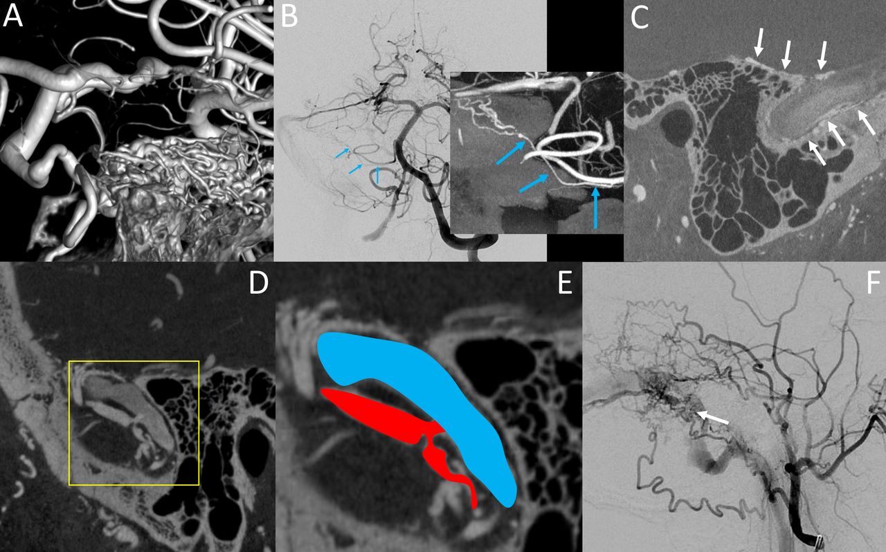
Different examples of image details that can be obtained with HR-CBCT in patients with dAVF. In A, volume rendered image intracranial view of the arteries supplying a petrous apex fistula; while the VR are aesthetically pleasant, rarely they provide useful clinical information. In B is an example of the supply to a right sigmoid fistula through the subarcuate artery from the AICA (blue arrows in B), a detail that would be very hard to identify on 2D-DSA but that can be retrospectively identified once it is understood on the coronal MIP HR-CBCT image. In C is a thin sagittal image from an HR-CBCT showing innumerable arteries in the wall of the sigmoid sinus (arrows) without evidence of a fistula hole. In D–F is another example of a dural fistula with sagittal HR-CBCT image showing the direct connection between the arterial arcade in the wall of the sinus and the sigmoid sinus, with inset from D magnified and schematized in E with (in red) the artery in the wall of the sinus and (in blue) the sigmoid sinus connected through a direct hole. This observation, which is hard to understand on the 2D-DSA (F), may lead to strategic superselective dAVF embolization via the venous approach. AICA, anterior inferior cerebellar artery; 2D-DSA, two-dimensional digital subtraction angiography; dAVF, dural arteriovenous fistula; HR-CBCT, high resolution cone beam CT; MIP, maximum intensity projection; VR, volume rendered images.

Elderly woman with cavernous dAVF. Common carotid artery (A) and selective ascending pharyngeal artery (B) 2D-DSA lateral projections showing a cavernous dAVF with supply from multiple ECA and ICA branches and exclusive cortical venous drainage, without ophthalmic or petrosal sinus drainage. The HR-CBCT was performed reconstructed in full VOI (C) and smaller VOI (D) also with volume rendered reformat (E), demonstrating well the primary fistula pouch (arrow in D) as well as showing the existence of a hypoplastic, partially thrombosed inferior petrosal sinus (arrow in C). Based on the HR-CBCT images, the decision was made to attempt a catheterization through the inferior petrosal sinus, which was successful, leading to fistula cure with a selective pouch coiling (G) and sparing the rest of the cavernous sinus, as shown in post-embolization common carotid artery angiography lateral projection subtracted (F) and non-subtracted (G). 2D-DSA, two-dimensional digital subtraction angiography; dAVF, dural arteriovenous fistula; ECA, external carotid artery; HR-CBCT, high resolution cone beam CT; ICA, internal carotid artery; VOI, volume of interest.
Stroke
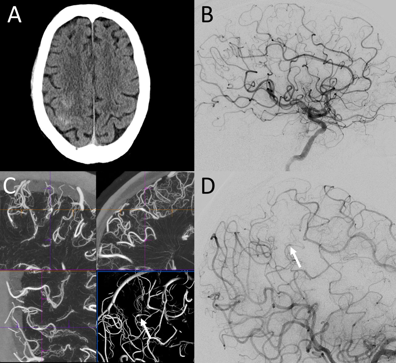
Traditional utilizations of non-contrast CBCT, either before the thrombectomy as a substitute of the traditional CT scanner or during/after the thrombectomy to rule out a hemorrhage, are very well detailed elsewhere.22 The roles of HR-CBCT angiography during stroke thrombectomy are infrequent. They include the evaluation of collaterals23 or the visualization of vessels distally to a point of occlusion, through an acquisition obtained during intra-arterial injection from the ascending aorta.24 HR-CBCT has also proved very useful to understand the underlying condition in situations of refractory or recurrent occlusion, being often able to allow the identification of intracranial atherosclerosis or dissection by visualizing the flap or the false lumen25 (figure 12).

Patient with history of trauma and left MCA inferior division ischemic infarct, presenting for angiogram to evaluate the intracranial vasculature. While 2D-DSA (A) clearly showed a stenosis of the inferior division of the left MCA, it is only by performing HR-CBCT with small VOI reconstruction (B–D), corresponding to the inset of figure A, that the anatomy of the vessel could be interpreted as being related to an intracranial dissection, with the false lumen terminating in a blind pouch (dotted arrows) and compressing the true lumen of the inferior division MCA, hence causing the stenosis (white arrows). 2D-DSA, two-dimensional digital subtraction angiography; HR-CBCT, high resolution cone beam CT; MCA, middle cerebral artery; VOI, volume of interest.
Miscellaneous
Generally, HR-CBCT has found a role in many other conditions as well, such as in the case of carotid-cavernous fistula (CCF) where the images obtained helped to understand the size of the hole and the potential venous pathways (figure 13). For vasospasm, this technique proved useful to identify precisely the foci of stenosis, offering insights into the pathophysiolgy of the condition.26 For middle meningeal artery embolization procedures in the setting of subdural hematomas,27 as well as for tumor embolization procedures,28 it can provide information on the collateral pathways and the arterial supply. For spinal vascular malformations, especially spinal dAVF, HR-CBCT has proved very useful in localizing the fistula and treatment planning by identifying in detail the radiculopial and radiculomedullary vessels in relation to the dAVF feeders.29 30

Direct traumatic cavernous fistula with lack of antegrade flow in the ipsilateral ICA (A) and collateral supply from the contralateral ICA (B). HR-CBCT performed through right ICA injection (C, D) showed very well the communication between the carotid artery and the cavernous sinus—schematized in the inset with the internal carotid artery (in red) and the cavernous sinus (in blue). Notice in D the filling of the contralateral cavernous sinus from the CCF through the intercavernous sinus with the filling defect of the left cavernous sinus structures such as the ICA and the cranial nerves (arrows). CCF; carotid-cavernous fistula; HR-CBCT, high resolution cone beam CT; ICA, internal carotid artery.
Exploration of normal anatomy
The images obtained to evaluate neurovascular diseases proved to be particularly rich in information to collaterally understand the normal neurovascular anatomy. While this is not the topic of this review, we point to other papers31–34 to further understand the role of HR-CBCT for this purpose.
Limitations
Limitations of the HR-CBCT technique include the length of acquisition which carries with it: (1) the requirement for complete paralysis; (2) a vascular phase limitation making it difficult to visualize only the arterial or only the venous phase; (3) the amount of contrast given, since the contrast opacification has to be even throughout the acquisition, a longer acquisition means a larger amount of contrast; (4) the amount of radiation, since longer acquisitions usually result in larger amounts of radiation.
Paralysis. While HR-CBCT can be obtained during any routine angiography, it is our experience that patient movement during the acquisition limits greatly the quality of the images obtained. If a high level of resolution is needed for diagnostic purposes, general anesthesia with breath hold should be used.
Vascular phase. The best images are provided using 20 s HR-CBCT, but acquiring a volume over 20 s makes it impossible to be able to separate the visualization of the arteries from veins, the so-called temporal resolution, typically thought of as a major advantage of catheter angiography. Most of the time this limitation is secondary since the distinction of the anatomic structures can be made by following the branches to their bigger parent vessels, but when trying to distinguish small perforators such as basilar perforators or white matter perforators, the task remains daunting. We believe that technological evolution in this perspective with faster CBCT acquisition with preserved resolution (such as for Siemens, the 8 s DynaCT on Icono vs the 20 s option on Artis Q) will result resolutory from this perspective. A 6 s protocol may be enough but a faster one (4 s) may be even more ideal, given the time of arterial to venous flow in the brain.
Amount of contrast. An acquisition of 20 s necessitates an injection of 40–70 mL of diluted contrast depending on the territory injected. It is certainly reasonable to try and limit the acquisition for situations of clinical interest. While contrast material-induced nephropathy is rare after cerebral angiography (possibly due to separation of total contrast material dose in time intervals, with small amounts administered during separate injections),35 we recommend against indiscriminate volumetric acquisition of multiple territories. It is possible that a relatively larger injection for CBCT angiography may increase the risk, but in our experience we did not have any such occurrence in patients with normal renal function. We have also not encountered any neurologic effects from high volume contrast injections.
Radiation. The radiation doses with current generation angiographic machines are remarkably lower than those with older generation equipment and a 20 s CBCT results in approximately 200 mGy (reference air kerma). Regardless, rotational angiography is associated with reduced radiation doses compared with 2D-DSA36 for a few reasons: the acquisition often allows for diminished utilization of 2D-DSA making the final total dose reduced; furthermore, the radiation is dispersed over multiple different projections, so even if the overall mGy is higher, the contribution of a CBCT acquisition to the maximum skin dose during a procedure is low. Certainly it is good practice to have the team temporarily leave the angio suite during the CBCT acquisition to limit the radiation exposure to personnel.
Conclusion
HR-CBCT angiography, which is available with any contemporary fluoroscopy machinery, is critically useful in certain clinical scenarios to improve the understanding of neurovascular anatomy and pathology, as well as guiding therapeutic decision-making. It is rapidly becoming an essential tool for the modern neurointerventionalist.
Supplemental material
Ethics statements
Patient consent for publication
Acknowledgments
We thank our team of stellar nurse practitioners Linda Warren and Mariya Naumoff, and our beloved assistant Xiomara Vargas. We also thank Zia Shamsi and Devin Lee from Siemens for their 24/7 support.
References
Supplementary materials
Supplementary Data
This web only file has been produced by the BMJ Publishing Group from an electronic file supplied by the author(s) and has not been edited for content.
Footnotes
Twitter @eytanraz, @ENossek
Contributors All authors made substantial contributions to the conception, design, data acquisition, data analysis, and data interpretation. ER drafted the manuscript and all other authors revised it critically and made substantial contributions. ER and MS acted as the guarantor. All authors approved the final version to be published. They agreed to be accountable for all aspects of the work in ensuring that questions related to the accuracy or integrity of any part of the manuscript are appropriately investigated and resolved.
Funding The authors have not declared a specific grant for this research from any funding agency in the public, commercial or not-for-profit sectors.
Competing interests ER, Siemens equity. DS, consultant Siemens.
Provenance and peer review Commissioned; externally peer reviewed.
Supplemental material This content has been supplied by the author(s). It has not been vetted by BMJ Publishing Group Limited (BMJ) and may not have been peer-reviewed. Any opinions or recommendations discussed are solely those of the author(s) and are not endorsed by BMJ. BMJ disclaims all liability and responsibility arising from any reliance placed on the content. Where the content includes any translated material, BMJ does not warrant the accuracy and reliability of the translations (including but not limited to local regulations, clinical guidelines, terminology, drug names and drug dosages), and is not responsible for any error and/or omissions arising from translation and adaptation or otherwise.