Article Text

Abstract
Object Little is known about how much protection a flow diversion stent provides to a non-thrombosed aneurysm without the adjunctive use of coils.
Methods A three-dimensional anatomically realistic computation aneurysm model was created from the digital subtraction angiogram of a large internal carotid artery-ophthalmic artery aneurysm which could have been treated with either a neck bridging stent or a flow diversion stent. Three-dimensional computational models of the Neuroform EZ neck bridging stent and Pipeline embolization device were created based on measurements with a stereo-microscope. Each stent was placed in the computational aneurysm model and intra-aneurysmal flow structures were compared before and after placement of the stents. Computational fluid dynamics were performed by numerically solving the continuity and Navier–Stokes momentum equations for a steady blood flow based on the finite volume method. Blood was assumed as an incompressible Newtonian fluid. Vessel walls were assumed to be rigid, and no-slip boundary conditions were applied at the lumens. To estimate the change in the intra-aneurysmal pressures we assumed that, at the inlets, the intra-arterial pressure at peak systole was 120 mm Hg both before and after stent placement
Results Without any stent, the blood flow entered into the aneurysm dome from the mid to proximal neck area and ascended along the distal wall of the aneurysm. The flow then changed its direction anteriorly and moved along the proximal wall of the aneurysm dome. In addition to the primary intra-aneurysmal circulation pattern, a counterclockwise vortex was observed in the aneurysm dome. The placement of a Neuroform EZ stent induced a mean reduction in flow velocity of 14% and a small change in the overall intra-aneurysmal flow pattern. The placement of a Pipeline device induced a mean reduction in flow velocity of 74% and a significant change in flow pattern. Despite the flow velocity changes, Neuroform EZ and Pipeline devices induced reductions in intra-aneurysmal pressure of only 4 mm Hg and 8 mm Hg, respectively.
Conclusions The flow diversion effects of both stents were limited to flow velocity reduction. In a non-thrombosed aneurysm or an aneurysm with delayed thrombosis, the intra-aneurysmal pressure remains essentially unchanged regardless of the level of the intra-aneurysmal flow velocity reduction induced by the stents.
- Aneurysm
- Flow Diverter
- Stent
- Blood Flow
Statistics from Altmetric.com
Introduction
There is an ever increasing use of intracranial stents for the treatment of wide-necked or fusiform aneurysms.1–3 A new type of intracranial stent—the flow diverter—has provided a new endovascular capacity to reconstruct both an intracranial aneurysm and its diseased parent artery.4–6 The flow diverter is constructed from high-density braided mesh which changes intra-aneurysmal hemodynamics without any coils and leads to obliteration of the aneurysm by inducing thrombus formation.2 ,5 ,7 ,8 Alteration of intra-aneurysmal flow was also observed by the placement of a conventional neck bridging stent for stent-assisted coil embolization.4–6 However, various studies based on experimental and computational methods have suggested that the effect of flow diverters on intra-aneurysmal hemodynamics is more robust.3 ,7–12
Some clinical complications such as delayed aneurysm rupture after the placement of flow diverters and a need for supplementary loose coil packing have recently been reported despite the high rate of complete aneurysm obliteration.3 ,10 ,12–14 The issue of delayed rupture did not emerge when stent-assisted coil embolization of intracranial aneurysms became a routine procedure. This is presumably because the coil mass provides primary protection to the treating aneurysms and the hemodynamic alteration by the neck bridging stent is adjunctive. It is known from clinical experience that the hemodynamic changes of neck bridging stents without any coils are not sufficient to protect saccular aneurysms. The question therefore emerges as to how much protection a flow diversion stent provides to an aneurysm during the initial non-thrombosed phase without the adjunctive use of coils. This fundamental question needs to be answered since not all aneurysms are completely obliterated immediately after the placement of flow diversion stents. We therefore studied the intra-aneurysmal hemodynamics effects of a Neuroform EZ self-expanding aneurysm neck bridging stent (Stryker Neurovascular, Fremont, California, USA) and a Pipeline embolization device (Covidien/ev3 Neurovascular, Irvine, California, USA) without any aneurysm coils. Both stents were placed in the same anatomically realistic aneurysm model, and the intra-aneurysmal hemodynamics including pressure were studied before and after placement of the stents. By using a neck bridging stent—which is known to provide no aneurysm protection by itself—as a hemodynamic comparison, this study approach enables assessment of the performance of a current flow diversion stent in terms of aneurysm protection.
Materials and methods
Model geometry
Three-dimensional (3D) computational models of the Neuroform EZ (non-flow diversion stent) and Pipeline (flow diverter) devices were created using Solid Edge software (Siemens PLM Software, Köln, Germany) based on the microscopic measurement with an Asone stereomicroscope (Asone Corporation, Tokyo, Japan). The Neuroform EZ is constructed from a Nitinol tube with a diameter, length, width and thickness of 4.5, 20, 0.065 and 0.07 mm, respectively (figure 1 upper left). The porosity of the Neuroform EZ ranges from 6.5% to 9.5% when placed in an appropriately sized artery. The geometric structure of the Pipeline device consists of 48 wires of 0.048 mm thickness, diameter 3.5 mm and length 20 mm (figure 1 lower right). The porosity of the Pipeline ranges from 30% to 35% when an appropriately sized Pipeline is placed in the parent artery of the treating aneurysm. Both the Neuroform EZ and Pipeline devices were placed within the computational aneurysm model using a virtual stent deployment technique (figure 2 middle and right).15 ,16 The diameters and lengths of the stents were determined by two experienced interventional neuroradiologists (ST and FV) after careful review of the aneurysm model.

Geometry of Neuroform EZ stent (upper left) and Pipeline device (lower right). Note that the porosity of the Pipeline flow diversion stent is much higher than that of the Neuroform EZ neck bridging stent.
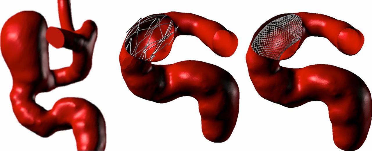
Three-dimensional model of an internal carotid artery-ophthalmic artery aneurysm reconstructed from a clinical case (left). A Neuroform EZ stent (middle) and Pipeline device (right) were placed across the aneurysm neck.
A large internal carotid artery-ophthalmic artery (ICA-OphA) aneurysm, which could have been treated with either a conventional aneurysm neck bridging stent or the Pipeline device, was selected from the 3D rotational angiography clinical database in our institution for the construction of the aneurysm model (figure 2 left). The 3D rotational digital subtraction cerebral angiogram of the ICA-OphA aneurysm was acquired using a Philips Integris unit (Philips Medical Systems, Best, The Netherlands). The aneurysm dome of the ICA measured 8.1 mm in the anteroposterior direction, 9.4 mm in the transverse direction and 11.5 mm in the craniocaudad direction. Based on the images of the digital subtraction angiogram, a geometric arterial model was constructed and transformed into a stereolithography geometric format by 3D-doctor modeling software (Able Software, Lexington, Massachusetts, USA). Our Institutional Review Board approved the use of angiographic data for the virtual stent placement and subsequent hemodynamic simulations.
Computational fluid dynamics
Computational fluid dynamics were performed by numerically solving the continuity and Navier–Stokes momentum equations for a steady blood flow using the commercial software Fluent (ANSYS, Canonsburg, Pennsylvania, USA), based on the finite volume method. Fluid volumetric mesh was created and defined by ANSYS ICEM for our simulations.10 ,17 Blood was assumed as an incompressible Newtonian fluid with a density of 1.06 g/cm3 and viscosity of 0.04 g/cm s. Inlet flow velocities were applied with 58 cm/s as steady flow. Vessel walls were assumed to be rigid, and no-slip boundary conditions were applied at the lumens. To estimate the change in the intra-aneurysmal pressures we assumed that, at the inlets, the intra-arterial pressure at peak systole was 120 mm Hg both before and after stent placement.10 ,17 The pressure distribution along the parent artery and in the aneurysm was then computed by using the falls in pressure calculated during the CFD simulations with respect to the p=0 value prescribed at the outlet.10 ,17 For this calculation, mesh dependency tests were performed in order to ensure the stability of the simulations; the final grids contained between 3 918 468 and 6 031 471 elements.
Results
Intra-aneurysmal flow pattern and velocity
Figure 3 shows the intra-aneurysmal flow patterns in the left anterior-oblique view without a stent with a Neuroform EZ stent and with a Pipeline device. Without any stent (figure 3, left) the blood flow entered into the aneurysm dome from the mid to proximal neck area and ascended along the distal wall of the aneurysm. The flow then changed its direction anteriorly and moved along the proximal wall of the aneurysm dome. In addition to the primary intra-aneurysmal circulation pattern, a counterclockwise single-vortex flow pattern was observed in the aneurysm dome.

Comparison of flow stream with no stent (left), Neuroform EZ stent (middle) and Pipeline device (right).
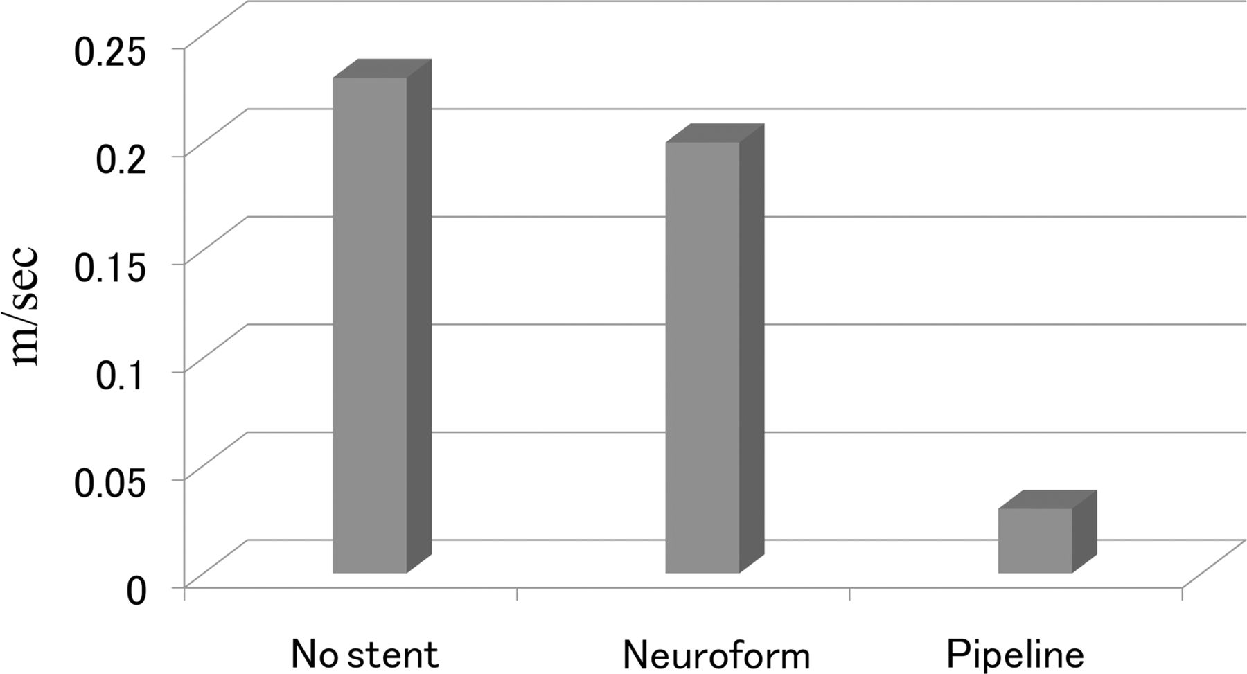
The placement of a Neuroform EZ stent induced a reduction in mean flow velocity of 14% compared with that without stent (figure 4). However, only a small change was observed in the overall intra-aneurysmal flow pattern compared with the pattern without a stent. The additional counterclockwise large single-vortex flow pattern observed in the aneurysm without a stent remained even after the placement of a Neuroform EZ stent (figure 3, middle). The placement of a Pipeline device induced significant changes in both intra-aneurysmal flow velocity and flow pattern. The mean flow velocity was reduced by 82% compared with that without the Pipeline device (figure 4). The secondary vortex observed in the aneurysm dome without a stent or with a Neuroform EZ stent disappeared with placement of a Pipeline device (figure 3, right).

Comparison plot of the mean intra-aneurysmal flow velocity with no stent (left), with a Neuroform EZ stent (middle) and with a Pipeline device (right).
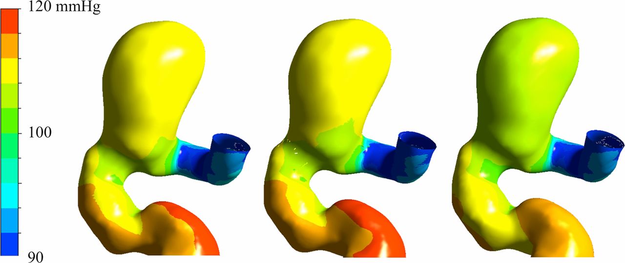
Despite the reductions in flow velocity and alterations in flow pattern with both stents, there was no significant difference in the intra-aneurysmal pressure. The placement of a Neuroform EZ stent induced a reduction in the mean intra-aneurysmal pressure of 4 mm Hg (figure 5, middle) and, following placement of a Pipeline device, the mean intra-aneurysmal pressure was decreased by 8 mm Hg (figure 5, right).

Comparison of pressure distributions in the aneurysm models with no stent (left), with a Neuroform EZ stent (middle) and with a Pipeline device (right).
Discussion
The introduction of intracranial stents has changed the way of treating wide-necked and fusiform aneurysms.1–3 The metallic scaffolding of a neck bridging stent combined with aneurysm coils enables reconstruction of the diseased parent artery with an aneurysm. Lately, a flow diversion stent, an endoluminal flow-disrupting device, has provided a new therapeutic approach to the treatment of very challenging intracranial aneurysms.4–6 ,13 Theoretically, a flow diversion stent is a stand-alone device that does not require coil embolization of the aneurysm.4 The first-generation flow diversion stent, the Pipeline device, has been used in clinical practice and the reported results are very encouraging in the neuroendovascular field. Lylyk et al reported their single-center experience with the Pipeline device in 53 patients with 63 intracranial aneurysms.6 Despite nearly half of the aneurysms being large or giant, complete angiographic occlusion of the intracranial aneurysms was achieved in 8%, 56%, 93% and 95% at the conclusion of treatment and at 3 months, 6 months and 12 months, respectively.6 The slow progressive thrombosis and the gradual increase in the rate of complete aneurysm obliteration over the follow-up period have also been observed in other clinical reports. Although the angiogram obtained immediately after treatment with a flow diverter may not show complete obliteration, the contrast transit time in the aneurysm becomes significantly slower and induces a layering of contrast material (eclipse sign).6
Clinical complications such as a delayed aneurysm rupture after the placement of a flow diversion stent have recently been highlighted in spite of the high aneurysm obliteration rate.6 ,13 ,14 Siddiqui et al reported on cases of delayed aneurysm rupture and recommended the use of coils in addition to a flow diversion stent.14 The delayed aneurysm rupture did not become a major issue for stent-assisted coil embolization presumably due to the protective effect of the aneurysm by the coil mass.
Our simulation study showed that the flow diversion effect is limited to a reduction in flow velocity (figure 3). There seems to be no significant difference in the intra-aneurysmal pressure between the aneurysm neck bridging stent and the flow diversion stent. In fact, our simulation suggested that neither neck bridging stents nor flow diversion stents reduce the intra-aneurysmal pressure (figure 5). In the treatment of an aneurysm with a neck bridging stent, the primary material that protects the aneurysm is the coil mass. The current study showed that the aneurysm neck bridging stent Neuroform EZ induced some flow diversion effects which could help the long-term durability of the subsequent aneurysm coil embolization. On the other hand, without a coil mass the aneurysm remains exposed to nearly normal arterial pressure during the slow process of progressive aneurysm thrombosis after placement of a flow diversion stent. While the mechanism of delayed aneurysm rupture after the placement of a flow diversion stent is not currently well understood, the fundamental issue is that the treatment of an aneurysm with a flow diversion stent alone is different from conventional aneurysm coiling in its inability to provide immediate aneurysm protection. Therefore, based on the pressure data in the present study, it has to be emphasized that the significant intra-aneurysmal contrast stagnation or the angiographic disappearance of the treating aneurysm immediately after placement of a flow diversion stent does not necessarily mean that the aneurysm is protected from the circulation system. Until future generation flow diversion stents that can elicit faster thrombosis and subsequent healing or intra-aneurysmal pressure reduction become available, the concomitant use of aneurysm coils with a flow diversion stent may have to be considered when immediate aneurysm protection or enhancement of the thrombosis process is necessary.17
This study has a few intrinsic limitations. Although we used anatomically realistic aneurysm models, a simulation study of one case does not provide a firm conclusion. Also, this study does not address one of the common treatment strategies of using multiple flow diversion stents to increase the stent strut density. Nevertheless, given the insignificant difference in the intra-aneurysmal pressure reduction between the Neuroform EZ and Pipeline devices, it is safe to speculate that the intra-aneurysmal pressure remains relatively high even with multiple overlapping flow diversion stents across the aneurysm neck. We are currently conducting direct aneurysmal pressure measurements in clinical cases under the approval of our institutional review board. This type of research approach is the first attempt to understand the complex mechanism of the aneurysm healing process after placement of flow diversion stents. Lastly, this study does not consider the biological aspect of the aneurysm healing process which occurs after the placement of flow diversion stents.
Conclusions
The changes in intra-aneurysmal flow caused by the placement of a Neuroform EZ stent and a Pipeline device were studied in the same anatomically realistic computational aneurysm model. The flow diversion effects of both stents were limited to flow velocity reduction. Significant intra-aneurysmal contrast stagnation immediately after the placement of flow diversion stents—the so-called ‘eclipse sign’—could give the misleading impression that the aneurysm is at least partially protected. This study shows that the intra-aneurysmal pressure remained essentially unchanged regardless of the level of reduction of the intra-aneurysmal flow velocity. A non-thrombosed aneurysm with a Pipeline device may be equivalent to a non-coiled aneurysm with a neck bridging stent in terms of the intra-aneurysmal pressure. Aneurysms without any signs of thrombus formation on follow-up studies may have to be managed as unprotected aneurysms.
Footnotes
-
Contributors All the authors contributed to the conception and design of the study or analysis and interpretation of data, drafting the article or revising it critically for important intellectual content and final approval of the version to be submitted.
-
Funding Japan Society for the Promotion of Science.
-
Competing interests None.
-
Provenance and peer review Not commissioned; internally peer reviewed.