Article Text

Abstract
Wide-necked bifurcation aneurysms (WNBAs) make up 26–36% of all brain aneurysms. Treatments for WNBAs pose unique challenges due to the need to preserve major bifurcation vessels while achieving a durable occlusion of the aneurysm. Intrasaccular flow disruption is an innovative technique for the treatment of WNBAs. The Woven EndoBridge (WEB) device is the only United States Food and Drug Administration approved intrasaccular flow disruption device. In this review article we discuss various aspects of treating WNBAs with the WEB device, including indications for use, aneurysm/device selection strategies, antiplatelet therapy requirement, procedural technique, potential complications and bailouts, and management strategies for residual/recurrent aneurysms after initial WEB treatment.
- aneurysm
- device
- flow diverter
- technique
This is an open access article distributed in accordance with the Creative Commons Attribution Non Commercial (CC BY-NC 4.0) license, which permits others to distribute, remix, adapt, build upon this work non-commercially, and license their derivative works on different terms, provided the original work is properly cited, appropriate credit is given, any changes made indicated, and the use is non-commercial. See: http://creativecommons.org/licenses/by-nc/4.0/.
Statistics from Altmetric.com
Background
Wide-necked bifurcation aneurysms (WNBAs) make up 26–36% of all brain aneurysms.1 The treatment of WNBAs remains technically challenging due to the need to preserve the major bifurcating vessels while still achieving a durable occlusion of the aneurysm.2
The Woven EndoBridge (WEB; Microvention/Terumo, Aliso Viejo, California, USA) was developed specifically for the treatment of WNBAs. The WEB device has been available for clinical use in Europe since 2011.3 In the USA the WEB device was recently approved by the Food and Drug Administration (US FDA) for the treatment of ruptured and unruptured wide-necked aneurysms of the anterior communicating artery (ACA) and middle cerebral artery (MCA), the internal carotid artery (ICA), and basilar artery bifurcations.
The WEB device is constructed of nitinol wires with a platinum core in a braided self-expanding mesh configuration (figure 1). Once placed in the aneurysm, the WEB device reconstructs the parent artery/aneurysm neck interface with a continuous low porosity metal mesh which disrupts flow within the aneurysm, initiating thrombosis, and providing a robust lattice for subsequent neoendothelial tissue overgrowth.4 5

Woven EndoBridge (WEB) devices: (A) Double Layer (DL); (B) Single Layer (SL); and (C) Single Layer Sphere (SLS). The WEB DL EV is a mesh sphere composed of 2 layers of braided nitinol/platinum wires. The inner and outer layers of braid are joined by proximal, middle, and distal platinum/iridium markers. The WEB SL EV and WEB SLS EV models are composed of single layers of braided nitinol. The braids are joined at the proximal and distal ends of the device by radiopaque platinum/iridium markers.
We present our experience with patient selection, technical use, and complication management derived from the US WEB-IT trial and initial commercial experience.
Aneurysm selection
Each WNBA must be analyzed individually for discrete anatomical and morphological features, which will determine its suitability for WEB device treatment.
Aneurysm sizes and morphologies amenable to WEB device treatment
Aneurysm sizes
Currently in the USA the smallest available WEB device is the 4 SLS (Single Layer Sphere), which is 4 mm (width) × 2.6 mm (height). Therefore, the smallest aneurysm amenable to WEB treatment must be at least 3 mm wide and 3.5–4 mm tall to accommodate this device. The largest available WEB is the 11 SLS, which is 11×9.6 mm and can be used to treat aneurysms measuring 9–10 mm in width and 9.5–10.5 mm in height.
The lower profile WEB 17 system is currently available in Europe and Australia. The WEB 17 SL (Single Layer) system is available in diameters ranging from 3×2 mm to 7×5 mm. The WEB 17 SLS system is available in diameters of 4–7 mm. Thus the 17 system can be used to treat smaller aneurysms. In addition, since the devices themselves are more flexible and are delivered through the lower profile VIA-17 microcatheter, aneurysm access and WEB device deployment are often considerably easier.6
Aneurysm shapes
The WEB systems are roughly spherical (SLS)/cylindrical (SL) in shape. As such, unilobular aneurysms with spherical, cylindrical, or ovoid shaped morphology are ideal for WEB treatment. However, WNBAs with irregular multilobular morphology can also be treated with the WEB by sizing the device to the primary lobe. A properly sized device will form a seal at the neck of the aneurysm and lead to thrombosis of the entire aneurysm, including any secondary lobes arising from the proximal primary lobe. The device can sometimes be used in conjunction with coils to hasten this progression, particularly with ruptured aneurysms. Irregularities or secondary lobules at the aneurysm neck may present a challenge to obtaining an adequate seal at the parent artery/aneurysm interface and lead to incomplete occlusion.
Aneurysm height axis-parent artery angle
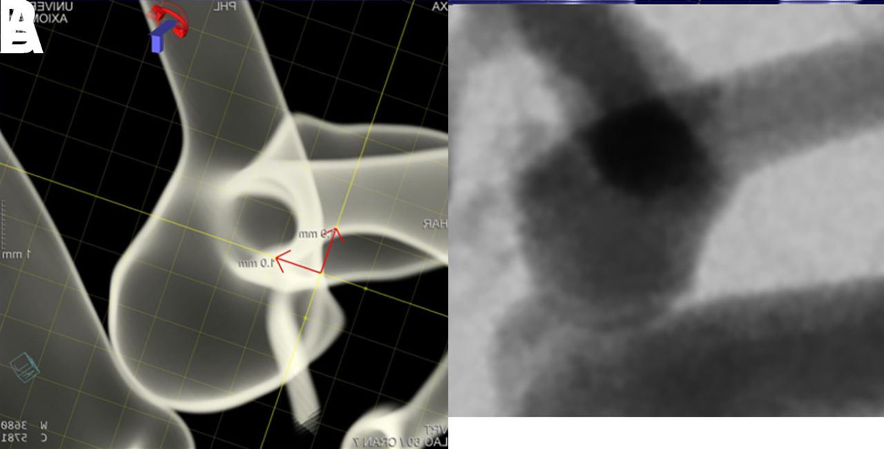
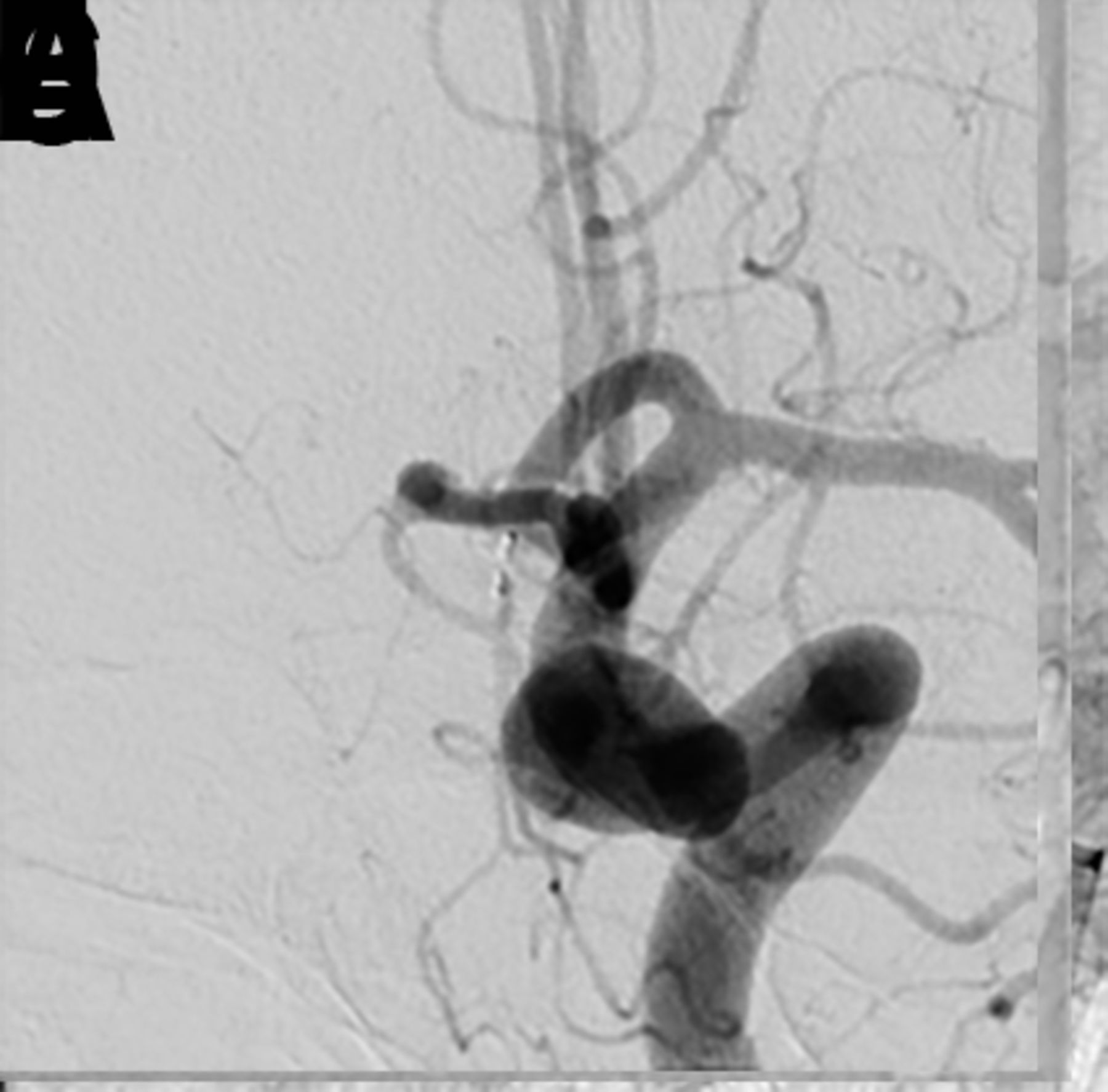
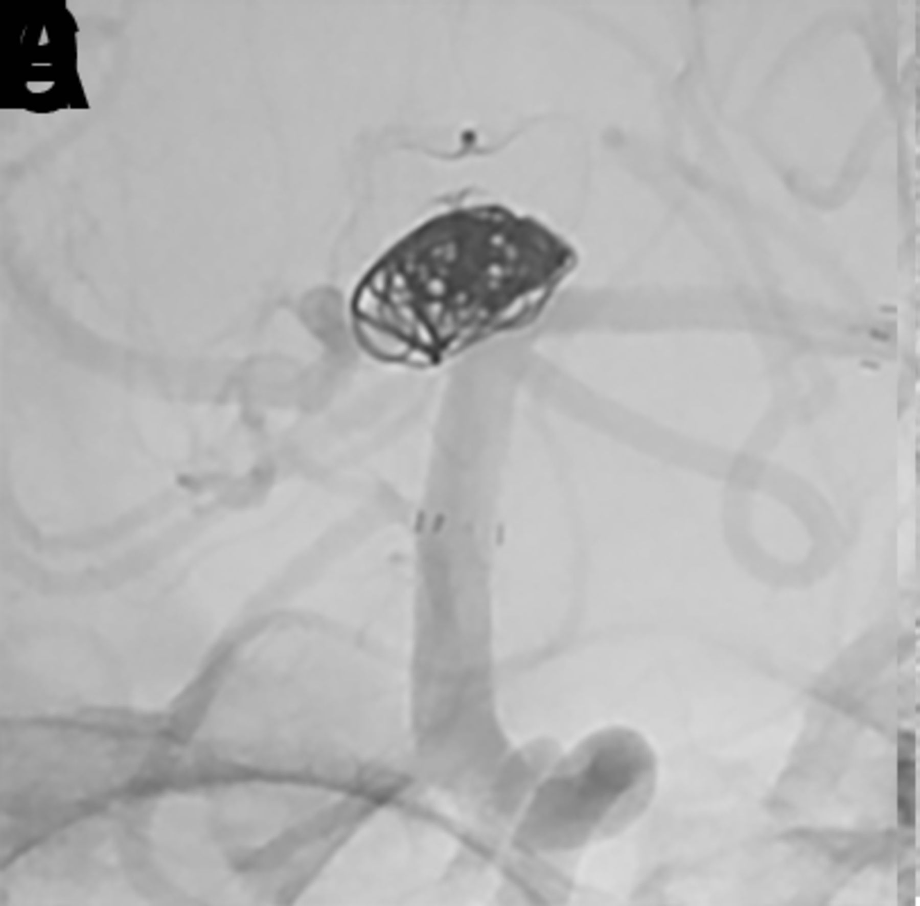
Both the dome size and the angle between the long axis of the aneurysm and the parent artery play a role in determining how easy or difficult WEB deployment will be(figure 2). WEB device delivery is most straightforward in large aneurysms without significant angulation between the proximal parent artery and the long axis of the aneurysm. The difficulty of both aneurysm catheterization and WEB device deployment is increased as this angle becomes more acute.
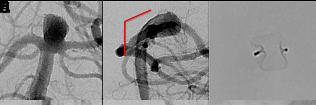
(A) Digital subtraction angiogram (DSA) of a patient with an incidental basilar apex aneurysm presented for WEB treatment demonstrating superiorly and upward projecting wide-necked basilar apex aneurysm. (B) There is a minimal angle between parent artery and aneurysm long axis (solid red line), making this an ideal case for WEB embolization. (C) Native DSA demonstrating successful deployment of the WEB within the aneurysm. (D) A patient with an incidental basilar apex aneurysm projecting superiorly and posteriorly, presented for WEB treatment. (E) There is an obtuse angle between parent artery and aneurysm long axis (solid red line), which requires extra attention when deploying a WEB device to avoid excessive friction between the device and the back wall of the aneurysm. (F) Native DSA demonstrating successful deployment of the WEB within the aneurysm.
Small aneurysms with an angulated access are the most challenging. For these aneurysms, the WEB 17 system is advantageous due to the greater softness of the device and the greater flexibility of the lower profile VIA 17 microcatheter. Steam shaping the VIA microcatheter is helpful for catheterizing aneurysms with extreme angulation at the parent artery/aneurysm interface.
Incorporated vessels
In general, the WEB device will 'self-center' as it expands within the fundus of the aneurysm, gently pushing off from the nearest wall into the center of the aneurysm. Ideally, the distal parent artery branch vessels arise symmetrically from the aneurysm neck. Parent artery branches arising from different locations at the proximal aneurysm neck are more challenging. Depending on the sizing and positioning of the WEB, the final treatment can result in either the creation of a dog-ear neck remnant (undersizing) or device impingement on one of the branch vessels (oversizing). These possibilities should be anticipated and accounted for during device selection. In these cases, the orientation of the expanded WEB device within the aneurysm can sometimes be manipulated by protecting one of the distal parent branch vessels with a balloon catheter during deployment. It is important to note that balloon inflation is not effective in repositioning a fully deployed WEB device; rather, it should be used during deployment before the WEB device is fully expanded. If reliable protection cannot be achieved with a balloon, it is often desirable to deploy the WEB device in conjunction with a microstent (figure 3). This technique allows for appropriate sizing to achieve a robust seal at the aneurysm neck without jeopardizing the patency of regional branch vessels.
(A) A patient with a prior history of subarachnoid hemorrhage caused by rupture of a posterior communicating artery aneurysm presented for WEB treatment of an enlarging unruptured basilar apex aneurysm. (B) Post-deployment native digital subtraction angiogram (DSA) demonstrating adequate positioning of the WEB SL within the aneurysm. (C, D) Post-detachment native DSA demonstrating change in orientation of the deployed WEB device causing mild impingement of the left posterior cerebral artery. A decision was made to deploy a LVIS stent (MicroVention, Terumo, Tustin, California, USA) to protect the left posterior cerebral artery. (E, F) Post-deployment flat panel cone-beam CT with reconstruction of the LVIS stent showing the WEB device within the aneurysm and patent LVIS stent spanning from the left posterior cerebral artery into the basilar artery.
Device selection
The WEB device has evolved from a dual-layer version (WEB DL) to high visibility single-layer versions (WEB SL and WEB SLS) (figure 1). The WEB SLS device is designed to treat bifurcation aneurysms with a fundus that tapers down at the neck to create a more spherical or ovoid appearance (an approximate 1.5:2 dome-to-neck ratio). The WEB SL device is barrel-shaped and designed to accommodate more cylindrical bifurcation aneurysms in which the aneurysm neck width and neck diameter are similar.
Radio-opaque marker bands demarcate the proximal and distal surfaces of the WEB device. These markers are slightly recessed into the body of the device—more so in the SL device than the SLS device—forming a flat (SLS) or concave (SL) 'marker recess' at the apex and at the parent artery/aneurysm interface.7 The proximal and distal recessed areas have the highest density of metal coverage, which approaches 100% metal coverage in the center and decreases radially to approximately 60–65% on average (depending on device sizing).
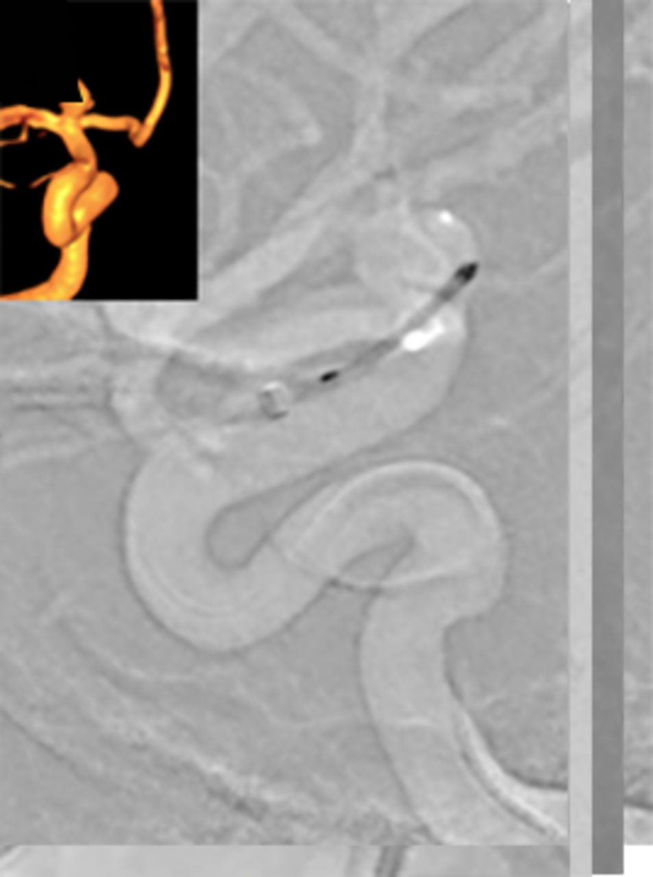
Appropriate WEB device size selection is of utmost importance for successful treatment. Treating physicians should obtain 2D and 3D angiographic images to measure the size (diameter, height, and neck width) of the aneurysm in at least two orthogonal projections. A 'down the barrel' view of branch artery anatomy is important in order to visualize and select the best sized device (figure 4). Once optimized working angle projections have been obtained, the physician should select the shape of the device (SL or SLS) based on the aneurysm size, neck, and dome morphology.

Three-dimensional (A, B) and two-dimensional (C, D) angiographic images of an incidental anterior communicating artery aneurysm prior to WEB treatment. The lateral three-dimensional (B) and two-dimensional (D) projections represent the 'down the barrel' view of the anatomyof the branch arteries so that an appropriately sized WEB device can be selected.
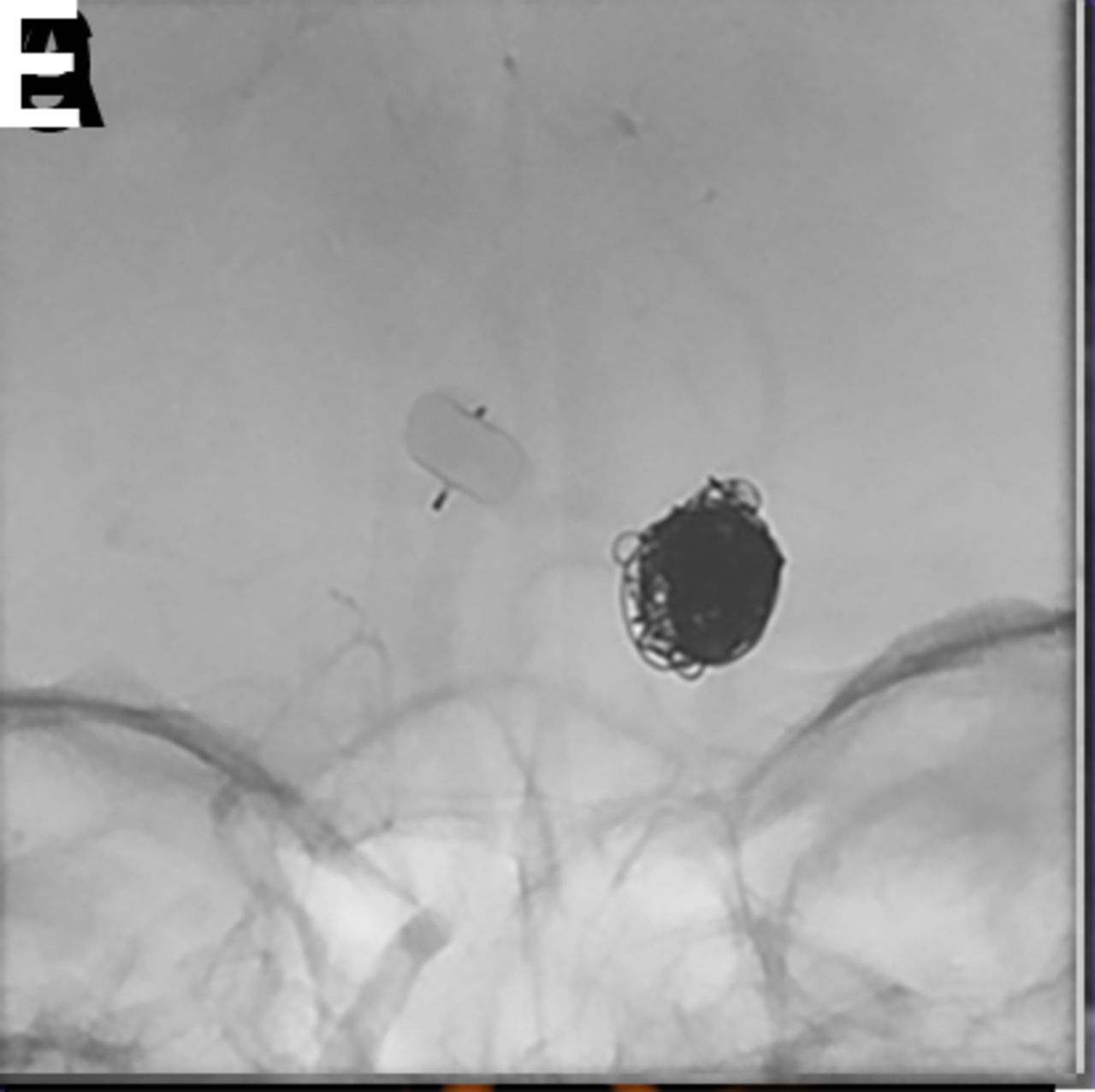
The WEB device is fully retrievable once deployed and may be exchanged for a different size or shape device if the original is not optimal. The device width should be oversized compared with the diameter of the aneurysm so that the radial force exerted by the WEB is distributed across the entire surface of the aneurysm wall. With oversizing, the WEB device braces itself against the aneurysm wall and bridges the neck completely. Compression in the width dimension results in increased height. Obtaining significant compression is critical to the function of the WEB device; inadequate compression is thought to be associated with an increased risk of aneurysm recurrence (figure 5).
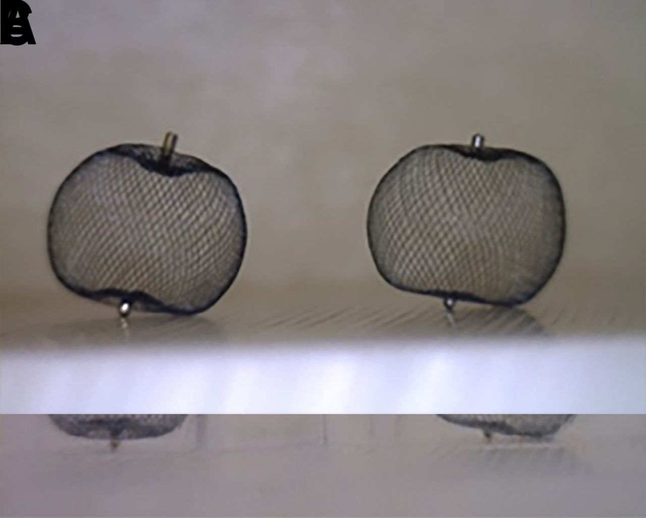
(A) Two identical SLS 7 WEB devices are shown. (B) One device was placed into a 6 mm tube, resulting in adequate compression and corresponding lengthening of the height of the device by 1 mm. The second device was placed into a 10 mm tube and was therefore not under lateral compression. (C) Identical weights were loaded onto the devices. The compressed WEB is able to maintain its shape under the load while the WEB that is not laterally compressed cannot maintain its shape.
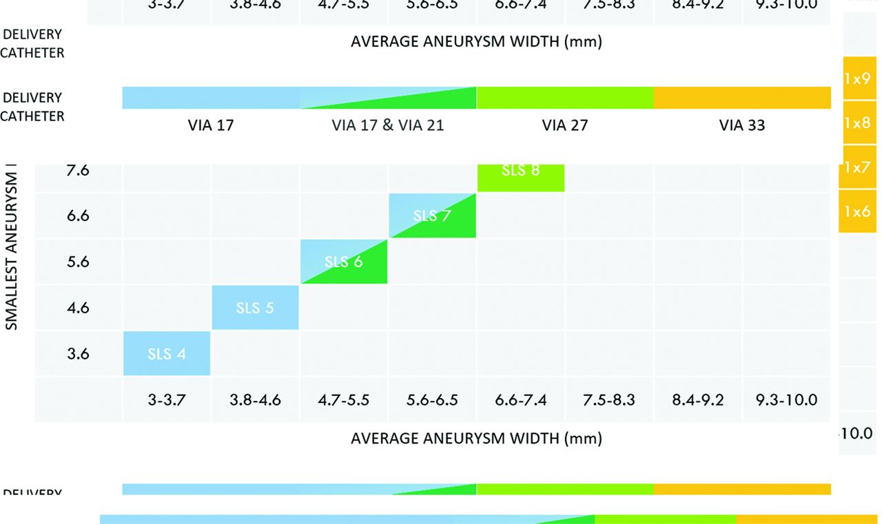
In general, the WEB device is best sized by adding 1–2 mm to the average width of the aneurysm in two dimensions. For small aneurysms, oversizing of approximately 1 mm is usually sufficient whereas, for larger aneurysms, 2 mm oversizing is recommended for a durable occlusion.8 Once the margin of width oversizing is established, the height of the selected device should be smaller than the average height of the aneurysm by a similar amount in order to adjust for the vertical growth of the device created by horizontal compression. WEB sizing should be calculated based on the expected position of the device within the aneurysm sac—that is to say, do not include the lobules that the device will not occupy into the measurements used to determine the size of the device. If the device is volumetrically larger than the aneurysm, it will typically elongate and may protrude into the parent artery at the aneurysm neck. If the device is markedly oversized, it will frequently not expand symmetrically and instead may take on an intussuscepted comma or crescent shape. In either scenario, the device can be removed and a smaller sized WEB device deployed.9 Figure 6 illustrates the availability of various WEB device sizes based on aneurysm sizes.

Different sizes of WEB SL and SLS devices available based on aneurysm sizes from Microvention’s library (note that the WEB 17 system is not approved in the USA). Top: WEB SL device selection table. Bottom: WEB SLS device selection table.
Antiplatelet medications
Ruptured aneurysms
Open surgical clipping for WNBAs is often used because available endovascular options for treatment require dual antiplatelet agents or may not result in adequate occlusion of the rupture site.9 10 Dual antiplatelet administration is not necessary with the WEB device when the entirety of the device is deployed within the aneurysm. It is also important to note that the collective experience to date has consistently demonstrated that the proximal marker of the WEB in the parent artery does not represent a significant thrombotic risk, as opposed to the mesh components of the WEB which can be quite thrombogenic if protruding into the parent vessel.
After the deployment of an appropriately sized WEB, rapid stasis can be achieved within the aneurysm in most cases. The braided nitinol structure of the WEB creates a very low porosity at the aneurysm neck/parent artery interface—more so than a mass of platinum coils—and thereby is expected to achieve at least an equivalent efficiency of aneurysm thrombosis. Clinical data have indicated that the application of the WEB device in ruptured aneurysms does offer reliable protection from rebleeding in the acute phase of subarachnoid hemorrhage.11
In most cases the authors prefer to treat ruptured aneurysms without pretreatment with antiplatelet medications. After the procedure, antiplatelet medications can be initiated in cases with a large aneurysm neck or if the device protrudes into the parent artery.
Unruptured aneurysms
For elective embolizations, pretreatment with effective antiplatelet therapy allows for the potential use of adjunctive stents if necessary, and may lower the risk of intraoperative thromboembolic complications.12 Under dual antiplatelet therapy, the collective experience suggests that the operator has sufficient operating time to fully assess a WEB device after delivery with standard angiography, rotational angiography, and/or cone-beam CT angiography prior to detachment. While no postoperative antiplatelet therapy is necessary in many straightforward cases, patients are often maintained on low-dose aspirin afterwards. In more complex cases, postoperative antiplatelet therapy is determined on a patient-by-patient basis.
Procedure
Access system
We recommend triaxial access: a long introducer sheath (6 Fr, 80 cm or 90 cm long, ≥0.088 inner diameter (ID)) is placed in the ICA or vertebral artery and a distal intermediate access catheter is placed in the intracranial portion of the ICA, vertebral artery, or basilar artery to provide intracranial support and microcatheterization of the aneurysm. There are a variety of intermediate catheters available that can be used.
The purpose-built VIA microcatheter (Sequent Medical, Aliso Viejo, California, USA) should be used for WEB deployment. It is a specifically engineered reinforced distal portion that allows recapture and redeployment, which may not be possible with other catheters. These catheters can be steam-shaped when necessary to facilitate aneurysm catheterization and achieve a stable intra-aneurysmal position during WEB device delivery. 4–7 mm WEBs can be delivered through a VIA 21 (0.021 inch ID), 8–9 mm WEBs can be delivered through a VIA 27 (0.027 inch ID), and 10–11 mm WEBs require a VIA 33 (0.033 inch ID).13 The VIA 17 (0.017 inch ID) microcatheter was developed to deliver the newest fifth generation WEB 17 system devices (3–7 mm in width).6
Introduction and deployment
Given the relative size of the microcatheters and overall stiffness of the platform, fluoroscopy during the entirety of device navigation through the microcatheter is recommended. Substantial movement of the VIA microcatheter both forward and backwards has been observed as the WEB device traverses through anatomical curves in tortuous anatomy. If care is not taken, this movement could result in either loss of microcatheter access within the aneurysm or perforation of the dome of the aneurysm. When the distal maker and catheter tip are aligned, it may be useful to pause and create a new roadmap to account for any regional anatomy distortion created as a result of the straightening caused by the constrained device within the microcatheter. It is important to remember that there is a roughly 1 mm non-radio-opaque segment of microcatheter beyond the distal marker band.
At this point, the device must be deployed so that it will 'blossom'. This deployment should be done slowly using a combination of unsheathing the device and pushing it out of the microcatheter. The decision to unsheath versus pushing out the device depends on a number of factors, including the stability of the access catheter, the location of the microcatheter within the aneurysm (shallow vs deep; centered vs against the aneurysm wall), and the axis angle of the parent vessel and long axis of the aneurysm. Prior to any device expansion the leading portion of the constrained device is rigid, and during this early phase of deployment any force exerted by the device will be distributed entirely at the interface between the tip and the aneurysm wall. In this early configuration, great care should be taken to avoid pushing the device forcibly against the aneurysm wall. Slow unsheathing of the initial portion of the WEB is required to allow the device to begin to expand (or 'blossom') prior to advancing it into position within the aneurysm fundus. Once partially expanded, the device becomes considerably softer and any forces exerted by the device on the aneurysm wall are distributed over a larger surface area.
Once the device has blossomed, it can be more aggressively positioned within the aneurysm. This is the beginning of the 'deployment window'—the period during which the operator can work to position the WEB device such that its inferior margin will align appropriately with the neck of the aneurysm. After this partial deployment, the WEB device will 'self-center', and then the pusher wire and microcatheter can be manipulated either together or independently to advance the WEB device in the fundus of the aneurysm and against the top of the dome (figure 7). In some cases, the device can be pushed aggressively against the dome to ensure it fills the distal aneurysm; in these cases, the partially deployed and compressed device may temporarily attain a comma-shaped configuration. Towards the end of deployment, gentle traction on the system will allow the WEB device to pop into a fully expanded configuration. At this point, the microcatheter can be unsheathed further to deploy the WEB device completely. The end of the deployment window is reached once the WEB device has been fully advanced from the microcatheter. Once deployed, the shape memory of the braided structure and friction between the deployed device and the aneurysm wall impedes efforts to significantly change the position or configuration of the device within the aneurysm.
(A–F) Because the microcatheter is against the back wall of the aneurysm, deployment of the WEB device via progressive unsheathing of the microcatheter and pinning the delivery wire is employed. This method allows the device to open without applying dangerous distal marker point force against the aneurysm wall. (G, H) Once the device is sufficiently open, it is soft enough to be repositioned within the aneurysm by advancing the pusher wire, which allows the WEB to better conform to the entire circumference and seal the neck. (I) Note that the axis of the device has been rotated in a counter clockwise fashion by this final maneuver (curved arrow). (J) Follow-up digital subtraction angiogram at 12 months demonstrating complete embolization of the aneurysm.
Prior to detachment, it is important to confirm that both the intermediate catheter and microcatheter are in a neutral position and not excessively loaded either forwards or backwards. If neutrality is not achieved prior to detachment, excessive microcatheter movement or device displacement may occur at the time of detachment.
Angiographic assessment
Post-deployment angiographic runs should be obtained to evaluate for appropriate sizing, lateral compression, and parent artery patency. If there is contrast passing around the device and into the aneurysm fundus, the WEB device should be removed and a larger diameter device should be used. In contrast, a slight extension of the mesh into the parent artery is usually tolerated. Extension of the marker band into the parent artery seems to be universally acceptable. Another critical aspect of device deployment is lateral compression. Once deployed, the WEB device needs to be compressed laterally for architectural stability (figure 8).

(A) Digital subtraction angiogram (DSA) demonstrating an unruptured left middle cerebral artery bifurcation aneurysm (5.4 mm wide × 6.3 mm high) prior to WEB treatment. An 8 mm × 3 mm WEB SL device was chosen for the treatment. (B, C) Post-deployment native DSA of the WEB device and (B) native program DSA demonstrating (C) the laterally compressed WEB device within the aneurysm without compromise of the branch vessel. Note that the width of the compressed WEB device is now 5.77 mm (decreased from 8 mm) with a height of 4.08 mm (increased from 3 mm).
Due to the structure and composition of the WEB device, a specific WEB device acquisition protocol was developed to enhance the visualization of the WEB device under two-dimensional native X-ray imaging post deployment (Siemens Healthineers, Forchhiem, Germany). This protocol is available on request for systems at or above version VC21 (figures 9 and 10).

(A) Post-deployment standard Neuro native digital radiography imaging without contrast of WEB device. (B) Standard Neuro native digital radiography imaging with contrast. (C) WEB native digital radiography imaging without contrast and (D) with contrast, enhancing the visualization of the WEB device.

(A) A patient with an incidental left middle cerebral artery (MCA) bifurcation aneurysm presented for WEB treatment. (B) Post-deployment standard digital subtraction angiogram (DSA) run demonstrating the proximal and distal markers of a deployed WEB SL device. (C) Post-deployment special WEB native program DSA run without and (D) with contrast, allowing better visualization of the device. (G) Dual volume three-dimensional DSA showing the shape of the deployed WEB device and its relationship with surrounding branch vessels.
A dual volume three-dimensional digital subtraction angiogram (DSA) or a flat panel cone-beam head CT with diluted contrast can be helpful in further evaluating the WEB in cases where the regional anatomy is complex. For the flat detector cone beam CT, a contrast dilution of approximately 20% typically provides an optimized visualization of both the regional parent vessel anatomy and the edges of the deployed WEB device (figure 10).13 14 It is important not to delay device retrieval excessively during device evaluation because thrombus may form in the device or aneurysm in the interim. This is of particular importance in cases performed without dual antiplatelet premedication (eg, ruptured aneurysms).
Detachment
The WEB device is detached using an electrothermal mechanism, similar to coils. Every effort should be made to ensure that the delivery system is in a neutral configuration with neither forward nor backward pressure on the deployed device. The VIA microcatheter should be retracted 1–2 mm proximally to the detachment zone. Detachment is performed under direct fluoroscopic visualization (often on a blank roadmap). A successful detachment is usually confirmed by visualization of a slight movement of the proximal marker band relative to the microcatheter tip.
Complications and bailouts
Parent artery impingement before device detachment
If parent artery impingement is noted on the post-deployment angiographic run, it may be related to either device size or positioning within the aneurysm. Remediation of this problem can be achieved by removing the device and trying a different size and/or shape or recapturing the device and redeploying it. Partial recapturing of the device to return to the 'deployment window' stage sometimes allows the operator to manipulate the device into a different position during deployment and achieve a different final deployed configuration. In most instances, a partial recapture and deployment deeper in the aneurysm is worth attempting before selecting a different sized device. As noted previously, balloons can sometimes be used to reposition or redirect the device during deployment.
Parent artery impingement after device detachment
In a few cases, the orientation of a deployed WEB device can change after detachment, leading to an unacceptable degree of parent artery compromise. Additional stenting is typically required in such cases (figure 3). As mentioned above, many patients undergoing elective WEB procedures are pretreated with dual antiplatelet agents in anticipation of the potential need for stenting. If substantial parent artery compromise is observed after the device shifts position following detachment, the microcatheter over a microwire can occasionally be used to push the device back into the aneurysm (figure 11). In cases of severe parent vessel impingement in which stenting is not feasible, the deployed WEB device cam be retrieved using an Amplatz gooseneck microsnare (Microvena Corp, White Bear Lake, Minnesota, USA).

(A) A patient presented for WEB treatment of an incidentally detected anterior communicating artery (ACA) aneurysm. (B) Post WEB SL detachment digital subtraction angiogram (DSA) showed adequate positioning of the WEB device within the aneurysm. While removing the VIA microcatheter, the inside of the catheter tip was brushed by the stem of the WEB, leading to backward movement of the WEB. (C) Follow-up native DSA demonstrating migration of the WEB device within the parent ACA. The decision was made to push the WEB device with the microcatheter and wire. (D) The WEB device was pushed within the aneurysm, as evidenced by the movement of proximal and distal markers. (E) Follow-up native angiography demonstrating adequate position of the WEB within the aneurysm. (F) Six-month follow-up DSA showing complete occlusion of the aneurysm.
Procedural rupture
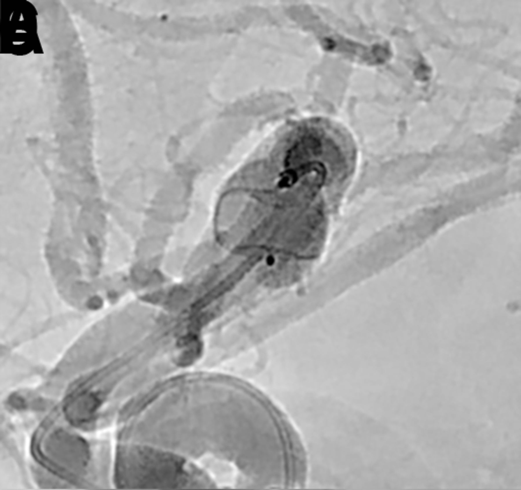
Rupture of the aneurysm with the relatively stiff VIA microcatheter, while rare, is a more common problem than rupture during WEB deployment. Rupture during WEB deployment usually happens at the moment when the constrained WEB device first exits the microcatheter. Once the WEB device is partially deployed inside the aneurysm, it is soft and aneurysm rupture is very unlikely to occur. If unanticipated forward pressure is stored within the VIA microcatheter and delivery system, forward movement of the microcatheter after WEB device detachment can also cause aneurysm rupture.15 At the time of rupture, if the WEB is already deployed but not detached, the device should generally not be removed as it usually creates efficient hemostasis. If the patient has received any anticoagulation therapy, it should be reversed immediately. Additionally, consideration of temporary balloon inflation in the parent artery is recommended to promote hemostasis if extravasation continues. In the WEB-IT study, only two patients suffered from periprocedural subarachnoid hemorrhage and neither experienced any permanent clinical sequel (figure 12).15 16

(A) A patient with an incidentally detected unruptured basilar apex aneurysm presented for WEB treatment. (B) Immediately after unsheathing a proximal Double Layer (DL) device, the microcatheter was advanced distally into the proximal aspect of the aneurysm. Follow-up digital subtraction angiogram (DSA) demonstrated a small amount of active contrast extravasation from the aneurysm dome. (C) Heparinization was reversed with protamine and a Hyperform 4 mm × 7 mm balloon (Medtronic, Irvine, California, USA) was transiently inflated within the distal basilar artery. (D) Repeat angiography demonstrated resolution of the extravasation. (E) Native DSA performed post-detachment demonstrating the WEB device well compressed in the aneurysm, leading to complete occlusion of the aneurysm without any branch vessel compromise. (F) Post-treatment flat panel cone-beam CT head showing a small amount of contrast extravasation within the interpeduncular cistern. The patient experienced no neurological sequelae from the transient extravasation.
Postoperative imaging and follow-up
Follow-up angiography is generally performed 6 months after treatment. Studies have suggested that contrast-enhanced or time-of-flight magnetic resonance angiography (MRA) is a useful screening procedure for WEB-treated aneurysm follow-up.17 However, MRA is not capable of providing reliable information on the WEB device lumen, presumably due to radiofrequency shielding.14 Therefore, DSA remains the standard for follow-up.
The WEB Occlusion Scale (WOS), based on the modified Raymond Scale, is an angiographic assessment scale developed to report aneurysm occlusion achieved with intrasaccular mesh implants.7 18 It is important to differentiate the filling of proximal marker recess from residual filling of the aneurysm neck. Studies have shown that this proximal marker recess is covered by dense neoendothelium after aneurysm occlusion with the WEB device.19 Thus, the filling of this marker recess area with contrast is an expected finding in completely occluded aneurysms with the WEB device.7 Residual neck is defined as the presence of contrast in contact with the aneurysmal neck that does not contact the wall of the aneurysmal sac or the inside of the WEB device, while the residual aneurysm is defined as apparent contrast in contact with the aneurysmal sac or inside the WEB device. Figure 13 demonstrates various WEB occlusion scales.
Web Occlusion Scale grades A and B indicate complete occlusion (A) with or (B) without an angiographically visible collection of contrast within the marker recess. (C) Residual neck filling is indicated by contrast opacification of the aneurysm neck extending beyond the expected bounds of the marker recess. (D) Residual aneurysm filling is indicated by contrast opacification extending beyond the aneurysm neck and into the fundus, either deep to the proximal marker recess or around the periphery of the device.
Treatment of residual/recurrent aneurysms
The long-term adequate occlusion rates of WNBAs after WEB device treatment reported in prospective trials exceed those reported for other endovascular modalities.20 However, a subset of patients may develop aneurysm recurrence and may potentially require retreatment. Two possible reasons for aneurysm recurrence are device migration and WEB device compaction.21
Device migration occurs when a WEB device moves from the initial site of placement into the aneurysm sac, but the aneurysm size remains stable. This phenomenon can occur due to an improperly chosen device or undersizing the device in very large or partially thrombosed aneurysms in which the WEB device is positioned (ie, 'corked') at the aneurysm neck. Migration is less likely to occur if the WEB device is under good compression at the aneurysm neck and is of adequate size to fill the aneurysm fundus sufficiently.
WEB device compaction is defined as a decrease in the height of the device with deepening of the marker recesses at both sides. This finding is relatively common and it is not necessarily related to undersizing the device, nor is it associated with aneurysm recurrence.22 This type of delayed configuration change results—on average—in approximately 30% height loss over time. This observation may indicate the formation of a stable scar or cicatrization within the aneurysm fundus that compacts the WEB device, but likely indicates durable occlusion of the fundus.23 In some circumstances, particularly in which the device is undersized, this compaction can result in aneurysm recurrence at the neck. Typically, these recurrences are small and often do not require retreatment.21 A case example of WEB device compaction is shown in figure 14.

(A) A patient presented for WEB treatment of an incidentally detected basilar apex aneurysm. (B) Post-detachment digital subtraction angiogram (DSA) of the WEB SL demonstrating adequate positioning of the WEB within the aneurysm. (C) Native DSA demonstrating adequate compression of the WEB within the aneurysm without any compromise of branch vessels. (D) Six-month follow-up native DSA demonstrating WEB compression caused by deepening of the device recesses at both sides, resulting in a neck residual.
WEB device treatment of WNBAs does not preclude retreatment of a recurrence. In some cases, stand-alone coiling may be performed by placing the microcatheter within the recanalized aneurysm lumen between the WEB device and the wall of the aneurysm. In many cases, recurrences are at the aneurysm neck, leaving a wide-necked shallow remnant. In these cases, conventional stent-assisted coiling remains feasible (figure 15). Early experience has also indicated that clipping residual or recurrent aneurysms after WEB treatment is also quite feasible.24

(A) A patient with an incidental basilar apex aneurysm presented for elective WEB treatment. (B) Immediate post-deployment digital subtraction angiogram (DSA) demonstrating adequate deployment of the WEB within the aneurysm. (C) Six-month follow-up DSA showing WEB compression and neck remnant. (D) Two-year follow-up DSA showing growing neck remnant. The decision was made to proceed with stent-assisted coiling of the neck remnant. (E) Immediate post-retreatment native DSA demonstrating coil mass within the neck remnant and stent spanning from the left posterior cerebral artery into the basilar artery. (F) Six-month follow-up native DSA.
Conclusion
Intrasaccular flow disruption with the WEB device is a safe and effective alternative to predicate endovascular treatments for WNBAs. As a new device class, there are patient selection criteria, technical factors, imaging factors, and complication avoidance and management strategies that are unique and should be emphasized in the early user experience.
Acknowledgments
The authors wish to thank Andrew J Gienapp (Neuroscience Institute, Le Bonheur Children’s Hospital and Department of Neurosurgery, University of Tennessee Health Science Center, Memphis, TN, USA) for technical and copy editing, preparation of the manuscript, figures, and videos for publishing, and providing publication assistance.
References
Footnotes
Twitter @AdamArthurMD
Contributors All authors of this work met ICMJE criteria for authorship and made substantial contributions to the conception and design, acquisition of data, analysis and interpretation of data, drafting, critical revising, and final approval of this manuscript.
Funding The authors have not declared a specific grant for this research from any funding agency in the public, commercial or not-for-profit sectors.
Competing interests NG reports no disclosures or conflict of interests. DH serves as a consultant for Covidien/Medtronic and Microvention outside of the submitted work and has received research support from Siemens. JD is an employee of Siemens Healthineers. LE serves as a consultant for Codman Neurovascular, Medtronic, MicroVention, Penumbra, Sequent, and Stryker outside of the submitted work. DF is a consultant for Balt, Marblehead, Medtronic, Stryker, Microvention, Stryker, Penumbra, and Cerenovus; receives research support from Cerenovus, Medtronic, Stryker, Siemens, Microvention, and Penumbra, and royalties from Codman; and is a stockholder for Marblehead, Neurogami, and Vascular Simulations outside of the submitted work. LP is a consultant for Balt, Microvention, Phenox, and Vesalio outside of the submitted work. SL is a consultant for Microvention, Medtronic, Stryker, Balt, Cerenovus, Cerus, Phenox, Neuroventures, and Oxford endovascular; and is a shareholder in Cerus endovascular outside of the submitted work. LS is a consultant for Balt, Microvention, Medtronic, Stryker and Cerenovus; receives research hospital support from Philips; and is a stockholder for Sensome and Sim & Cure outside of the submitted work. IS is a consultant for Medtronic and Sequent/Microvention outside of the published work. SC serves as consultant for Medtronic, and Sequent/MicroVention outside of the submitted work and is a stockholder in ELUM and NDI. ASA is a consultant for Balt, Johnson and Johnson, Leica, Medtronic, Microvention, Penumbra, Scientia, Siemens, and Stryker; receives research support from Microvention, Penumbra, and Siemens; and is a shareholder in Bendit, Cerebrotech, Endostream, Magneto, Marblehead, Neurogami, Serenity, Synchron, Triad Medical and Vascular Simulations outside of the submitted work.
Patient consent for publication Not required.
Provenance and peer review Not commissioned; externally peer reviewed.