Article Text

Abstract
Background Since its introduction, digital subtraction angiography has been considered the gold standard in diagnostic imaging for neurovascular disease. Modern post-processing techniques have made angiography even more informative to the cerebrovascular neurosurgeon or neurointerventionalist. Open neurosurgical procedures such as aneurysm clipping, extirpation of arteriovenous malformations, and extracranial–intracranial bypass remain important techniques in the armamentarium of a comprehensive cerebrovascular neurosurgeon. In-depth study of the anatomy of vascular pathology prior to and after surgery, often via selective cerebral angiography, is a critical component of surgical planning. However, when a vascular lesion or relevant anatomical region is perfused by two or more vascular territories, each selective angiographic imaging volume may provide an incomplete anatomical picture.
Methods An institutional database was searched for cases in which the syngo Inspace 3D–3D fusion software was used and assisted in diagnosis and surgical management.
Results In the six cases reviewed, the 3D–3D fusion imaging was crucial in understanding the anatomy of the vascular lesion and aided in surgical decision-making. The cases included two unique anterior communicating artery aneurysms, an arteriovenous malformation, an extracranial–intracranial bypass, and an angiographically negative subarachnoid hemorrhage.
Conclusions This is a novel strategy of combining two independently acquired selective cerebral angiography volumes to create a more accurate representation of the vascular anatomy. Given the increasing availability of the relevant image acquisition and processing technologies, we propose this strategy as a valuable adjunct in cerebrovascular procedures.
- Aneurysm
- Arteriovenous Malformation
- CT Angiography
- Angiography
- Subarachnoid
Statistics from Altmetric.com
Introduction
Cerebral angiography was developed in the early 20th century, but the associated equipment and image processing software has evolved rapidly in recent years.1 For complicated open and endovascular cerebrovascular procedures, a carefully performed and analyzed cerebral angiogram plays a crucial role in operative planning. Various image acquisition and processing techniques have been used in conjunction with cerebral angiography for improved visualization of vascular structures in diagnostic studies. Although now accepted as standard, the introduction of two-dimensional digital subtraction angiography (2D-DSA) in the early 1980s was a technological milestone which facilitated improved visualization of cerebral vessels after real-time subtraction of bony topography.2
While 2D-DSA remains the gold standard for evaluating vascular anatomy, numerous limitations exist, including overlapping anatomy and vessel foreshortening.3 These shortcomings were partially addressed with the development of rotational three-dimensional digital subtraction angiography (3D-DSA).3 Capable systems now take advantage of software-driven real-time subtraction of bony topography in serial rotational planes to perform 3D reconstruction of vascular anatomy. The images obtained with this technique often have superior spatial resolution compared to 3D images obtained via CT or MR angiography. As such, 3D-DSA has aided cerebrovascular neurosurgeons in planning and performing surgical treatments for pathologies such as cerebral aneurysms and arteriovenous malformations.
Yet in numerous circumstances, surgical planning is complicated by a vascular lesion receiving contributions from two or more major vascular territories. In the past, a simultaneous dual catheter, dual vessel angiography technique was used to visualize such complex structures.4 However, this approach adds procedural complexity and risk, with the need for additional vascular access and a second simultaneous injection of contrast. In addition, information regarding the individual contributions of each vascular territory is not demonstrated. If a neurosurgical intervention warrants knowledge of the exact vascular anatomy or relative contributions of two vascular territories, the combination of 3D-DSA imaging from two or more selective injections can provide significant benefits. In this study we explored this technique, referred to as ‘3D–3D fusion’, and discuss several case examples to demonstrate its utility.
Methods
Procedures
All cerebral angiographic studies and cerebrovascular surgeries were performed at Baylor St Luke's Medical Center in Houston, Texas, USA, after obtaining appropriate consents. Cerebrovascular surgical procedures as well as angiography procedures were performed using established techniques.
Image acquisition
Three-dimensional DSA images were acquired using a 5 s DSA head protocol on a Siemens flat-panel C-arm angiography system (Artis zee bi-plane, VC14J and VC21, Siemens Medical Solutions USA). During the 200° rotation, projection X-ray images were acquired before and after contrast injection (mask and fill acquisitions, respectively). 3D digitally subtracted images were automatically reconstructed and visualized as volume-rendered images using a dedicated clinical workstation. If needed, a 3D subtraction reconstruction algorithm with motion correction was applied to correct for misalignments between mask and fill acquisitions. For the 3D-DSA acquisition, 18 mL of undiluted contrast agent (Omnipaque 300 mg/ml) was power-injected at a rate of 2.5 mL/s at 800 psi with a 2 s X-ray delay. In cases where evaluation of a lesion with dual vascular supply was required (those highlighted in this report), separate 3D-DSA images were acquired with selective injection of contrast into each parent vessel.
Image fusion
Two 3D-DSA reconstructions corresponding to two selective injections into relevant vascular territories were used for image fusion in each patient. Each 3D-DSA acquisition was reconstructed as a native mask volume containing unsubtracted bony anatomy information. To fuse the two 3D datasets, the two native mask volumes were co-registered using automatic software alignment based on bony anatomical features. Manual adjustments were made if necessary to enhance the alignment of the two native mask volumes. This process was carried out on the clinical workstation using the provided software tool (syngo Inspace 3D–3D fusion). Upon co-registration of the two native mask volumes, the 3D-DSA volumes were automatically fused and visualized together as a pseudo-colored dual volume 3D image. This final fused imaging volume was then used for operative planning and evaluation. The software tool is available as an additional package for purchase (Siemens Medical Solutions, Malvern, Pennsylvania, USA).
Illustrative case examples
Case 1: Anterior communicating artery aneurysm: operative planning and relevant anatomy
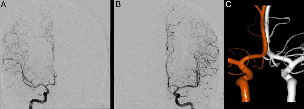
A patient with a history of hypertension presented with a 1 day history of severe headache and blurry vision. CT imaging of the head demonstrated subarachnoid and intraventricular hemorrhage with early hydrocephalus. Cerebral angiography was performed, which revealed an anterior communicating artery (ACoA) aneurysm as well as three other cerebral aneurysms. It was unclear which aneurysm had ruptured. Biplane imaging of selective right and left internal carotid artery injections each demonstrated two A2 vessels arising from the ACoA complex, injections each demonstrated suggestive of only two A2 vessels. 3D–3D fusion reconstruction of selective right and left internal carotid artery injections showed three A2 vessels arising from the ACoA complex with the posterior vessel feeding bilateral medial parietal cortices. The anticipation of three A2 vessels was invaluable in operative planning and execution. The patient underwent a left orbitozygomatic craniotomy for clipping of the ACoA as well as three other aneurysms. Postoperatively, the patient remained at her neurological baseline (figure 1).

(A) Anteroposterior (AP) view of a right internal carotid artery (ICA) injection showing two A2 vessels. (B) AP view of a left ICA injection showing two A2 vessels. (C) 3D–3D fusion reconstruction showing three A2 vessels in close proximity to the inferiorly projecting aneurysm of interest. Three-dimensional reconstructions based on injections of the right ICA (red) and left ICA (white) have been fused. The accessory vessel is seen in an intermediate color due to its bilateral contributions.
Case 2: Posterior temporal arteriovenous malformation: operative planning
A patient with a history of hypertension presented with headaches, dysphasia, and cognitive difficulty. CT and MRI of the brain, and subsequent cerebral angiography, demonstrated an unruptured right posterior temporal Spetzler–Martin grade III arteriovenous malformation (AVM),5 with feeders from the right middle cerebral artery (MCA) and right posterior cerebral artery (PCA) territories. She underwent partial Onyx embolization of her AVM through both MCA and PCA feeders with plans for subsequent surgical extirpation. The residual nidus received significant flow from the remaining MCA and PCA feeders. Dual-volume reconstruction of selective right internal carotid artery and vertebral artery injections showed approximately equal contribution of each feeder to the nidus but differential contribution to draining veins (figure 2). 3D–3D fusion visualization assisted with operative planning and with prioritizing the order of vessels to be coagulated during surgery. The patient underwent a right temporal craniotomy procedure for extirpation of her AVM, which was completed without complication. Postoperatively, she had an intact neurological examination. A cerebral angiogram was performed on postoperative day 3 which showed no residual filling of the nidus and complete resection of the AVM.
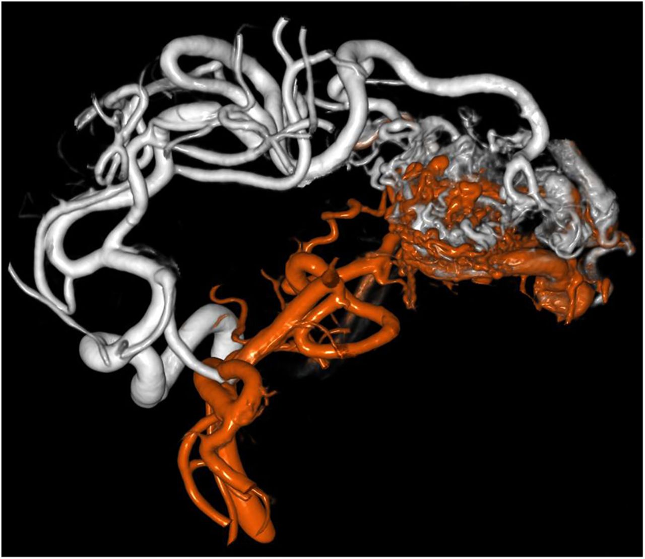
3D–3D fusion reconstruction combining two separate three-dimensional digital subtraction angiograms from injections of the right internal carotid artery (white) and right vertebral artery (red). The entire arteriovenous malformation (case 2) with its different feeder vessels can be well visualized in a single image.
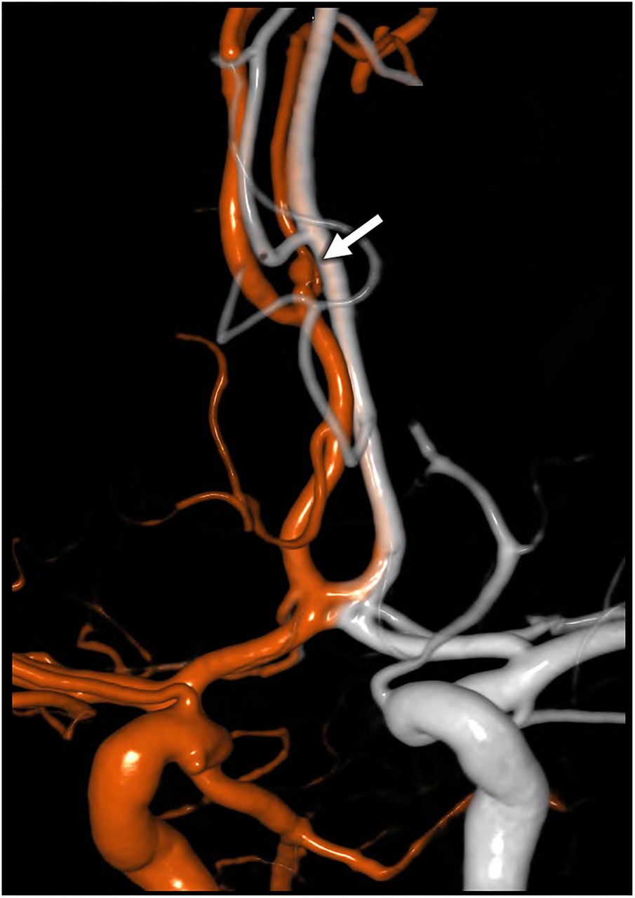
Case 3: Superficial temporal artery to MCA bypass: postoperative evaluation
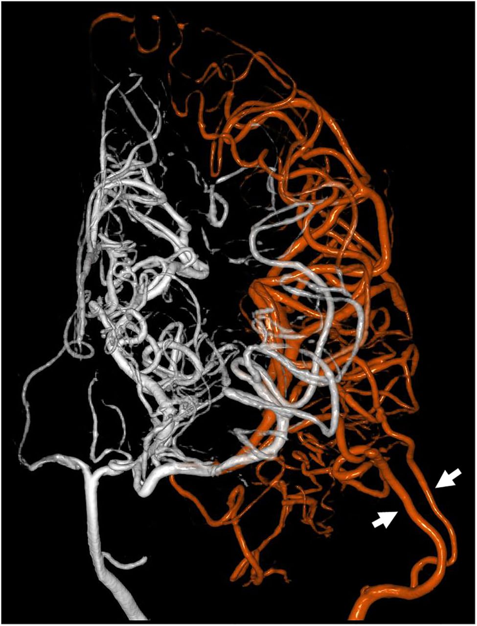
A patient with a history of moyamoya disease presented with headaches and transient ischemic attacks. The patient's symptomatology and radiographic findings indicated that the left side of the brain was more severely affected by the disease. A preoperative cerebral angiogram demonstrated delayed perfusion of the left MCA territory through pial collateral vessels from the PCA. The patient underwent a double-barrel left superficial temporal artery to left MCA bypass procedure.6 Postoperatively, the patient's neurological examination remained at baseline (non-focal). A CT perfusion with acetazolamide challenge showed improved perfusion of the left side of the brain, and a postoperative angiogram demonstrated patency of the double-barrel bypass. To further understand the relative contributions of the bypassed MCA branches to the left-sided MCA territory previously fed via PCA collaterals, a 3D–3D fusion reconstruction of selective left vertebral artery and left external carotid artery injections was performed. This dual-volume visualization demonstrated that the double-barrel bypass supplied the majority of the inferior division of the left MCA territory perfusion while collaterals through the posterior communicating artery irrigated the superior division of the MCA (figure 3). The patient was discharged without any focal neurological deficit on hospital day 7.

Postoperative 3D–3D fusion reconstruction from a patient who had undergone superficial temporal artery/middle cerebral artery bypass. The three-dimensional digital subtraction angiogram volumes from the left internal carotid artery (white) and left superficial temporal artery (red) were combined, allowing for easy evaluation of the perfused territories (case 3). Arrows demonstrate the two “barrels” of the superficial temporal artery used for anastamosis.
Case 4: Angiographically-negative aneurysmal subarachnoid hemorrhage
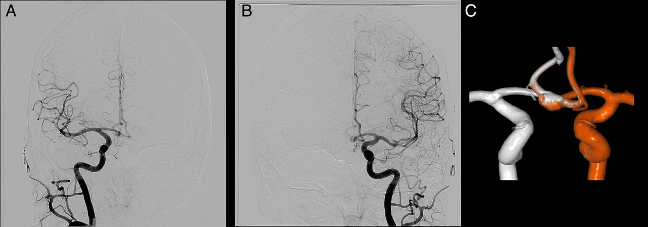
A patient with a history of diabetes, hyperlipidemia, and hypertension presented with sudden onset of severe headache with nausea/vomiting. CT imaging of the head without contrast showed diffuse subarachnoid hemorrhage (SAH) involving the suprasellar and prepontine cisterns, without midline shift or hydrocephalus, suspicious for aneurysmal SAH. An angiogram including 3D rotational angiography for each vascular territory was performed to look for a cerebral aneurysm. None was seen, but the ACoA was incompletely visualized. There was incomplete or limited cross-filling from each side. Rather than perform another angiography run with cross-compression to try to clear the ACoA, we performed a 3D–3D fusion and achieved a complete picture of the ACoA complex with its contribution from each side (figure 4). Thus, a causative aneurysm was more definitively excluded.
(A) Left internal carotid artery (ICA) injection digitally subtracted angiogram (DSA), anteroposterior view. Although the left A2 is seen, there is limited cross-filling across the anterior communicating artery (ACoA) and thus it is poorly visualized. (B) Right ICA injection DSA anteroposterior view shows essentially no cross-filling and the ACoA is not seen. (C) 3D–3D fusion reconstruction of individual injections from the right ICA (white) and left ICA (red), posterior view. In this patient with subarachnoid hemorrhage without a visualized aneurysm, complete visualization of the ACoA region was necessary but not fully achieved with traditional DSA left ICA (red). 3D–3D fusion allowed for excellent visualization to definitively exclude the presence of an aneurysm.
Case 5: Anterior communicating artery aneurysm: improved visualization
A patient with a history of controlled hypertension and hyperlipidemia presented with a 10 min episode of left-sided numbness without any weakness, which resolved by arrival to the hospital. CT imaging of the head without contrast was negative for SAH. MR angiography, done primarily for ischemic stroke/transient ischemic attack investigation, showed a poorly defined saccular flow void in the ACoA region with ill-defined margins. Selective injections of the bilateral common carotid arteries revealed an incompletely characterized ACoA aneurysm versus anatomical variation. 3D–3D fusion reconstruction allowed for excellent visualization of a 5×6 mm irregular ACoA aneurysm which was noted to have multiple Murphey's teats (figure 5).
(A) Left internal carotid artery (ICA) injection angiogram, anteroposterior view, showing partial filling of an anterior communicating artery (ACoA) aneurysm. (B) Right ICA injection angiogram, anteroposterior view, shows the same, without full visualization of the aneurysm. (C) 3D–3D fusion reconstruction consisting of three-dimensional digital subtraction angiogram volumes from the left common carotid artery (red) and right common carotid artery (white) injections. Whereas individual injections did not characterize the aneurysm well, with the combined fusion image the ACoA aneurysm is well visualized (case 5).
Case 6: Distal anterior cerebral artery aneurysm
A patient with a past medical history of hyperlipidemia presented to the hospital after experiencing the worst headache of her life and sudden-onset neck pain radiating to her head, in addition to weakness and lethargy. A CT scan of the head showed SAH. The patient was admitted to the neurointensive care unit and an external ventricular drain was placed. Subsequent four-vessel angiography showed a distal right A2 segment aneurysm. Due to the presence of multiple vessels in this field, a 3D–3D fusion of two-vessel selective cerebral angiography (left and right internal carotid artery) was performed, assisting in visualization of this aneurysm and its relation to the surrounding vessels (figure 6). During surgery, the interhemispheric fissure was tight due to swelling of the surrounding brain. In the deep and narrow operative corridor of the interhemispheric approach, with numerous vessels in close vicinity, the preoperative anatomic visualization from the 3D–3D fusion was especially useful.

3D–3D fusion reconstruction consisting of three-dimensional digital subtraction angiogram (3D-DSA) volumes from the right internal carotid artery (red) and left internal carotid artery (white) injections. The distal A2 segment aneurysm (arrow) was seen on individual DSA injections. However, 3D-DSA showed that indeed it was arising from the right A2, and 3D–3D fusion allowed visualization of nearby vessels including those from the contralateral A2 and A3 (case 6).
Discussion
Three-dimensional angiographic modalities such as CT and MR angiography which take advantage of intravenous injection and intracardiac mixing of the contrast agent provide for visualization of the entire cerebrovascular tree with a single injection. CT and MR angiography are readily available and offer proven value in diagnosing vascular pathology.7–9 However, 3D flat-panel detector DSA is still considered the gold standard against which the sensitivity and specificity of other modalities are measured. For instance, the sensitivity of CT angiography in detecting cerebral aneurysms suffers when aneurysms are smaller than 3 mm.10 ,11 Recent advances in flat-panel angiographic systems, with improved spatial resolution and more sophisticated 3D image reconstruction algorithms, have enabled enhanced visualization of cerebrovascular anatomy at a reasonable radiation dose.12 However, 3D-DSA typically relies on intra-arterial injection of contrast which provides more selective visualization of a limited vascular territory. As discussed in the selected cases above, vascular lesions or structures of interest are frequently supplied by more than one vascular territory. If one typically relies on catheter angiography and 3D-DSA for preoperative or postoperative evaluation due to its superior spatial resolution, one is typically limited to visualizing one vascular territory at a time. The neurosurgeon then has to mentally construct the full vascular structure from two or more selective 3D-DSA images, which can be difficult, inefficient, and prone to error.
The 3D–3D image fusion technique provides a way to automate the task of combining two selective 3D-DSA image volumes by taking advantage of the common bony features that are normally subtracted out of the DSA image. By maintaining the bony features in a separate linked volume and matching the relative coordinates of these bony features, the software aligns the two 3D-DSA image volumes. It also allows manual adjustments to fine-tune the alignment. Each image volume is depicted using a different color, and overlapping vessels typically show traces of both colors. The automatic alignment algorithm is robust, and in our experience performing over 100 3D-DSA image fusions, we were able to obtain precise alignment in all cases.
One drawback of this image fusion approach is that it requires at least two 3D-DSA image acquisitions leading to an additional radiation dose to the patient compared with single acquisition techniques such as a single run of 3D-DSA or a CT angiogram. However, the additional information obtained and the superior spatial resolution of 3D-DSA compared to CT angiography can outweigh the risk of additional radiation in some clinical settings.
The cases included here represent a small sample of the situations in which dual-volume 3D reconstruction has been particularly useful. Another example in which this could be useful would be fenestration of the ACoA, which is rarely well visualized with individual volume 3D rotational angiography.13
The diagnostic investigation in case 4 did not yield any aneurysms. However, with the use of fusion reconstruction of 3D-DSA, the inpatient investigation can be considered more thorough.14 Delgado Almandoz et al,15 in their study of catheter angiography-negative SAH, cite “the lack of rotational angiography with 3D reconstructions in the initial catheter angiogram in all patients” as a contributor to the rate of false-negative imaging. The 3D–3D fusion technique adds little risk or radiation, therefore we would propose more liberal use of 3D-DSA (referred to as 3D-DRA by others), with 3D–3D fusion when applicable.
While the current version of the software does not accommodate fusing more than two image volumes, this algorithm could be extended to allow the fusion of multiple 3D-DSA image volumes. For instance, an AVM supplied by the left MCA, left PCA, and left middle meningeal artery could be reconstructed using 3D-DSA acquisitions of selective injections of the left internal carotid artery, left vertebral artery, and left external carotid artery. Another potential avenue of development could consist of fusing single or multi-volume 3D-DSA images to other imaging modalities such as MRI. The design and implementation of such software algorithms is feasible, as CT images containing bony features are routinely fused with MRI images for intraoperative navigation and stereotactic applications.16–19 Among several potential uses, one could employ 3D-DSA to MRI fusion images for precise identification of anatomic structures near an AVM and for intraoperative guidance to particular feeder vessels.
Conclusions
The rapid pace of development in catheter angiography devices and image processing software over the past decade has allowed higher resolution, selectivity, and efficiency in acquiring images while lowering the amount of radiation needed to obtain the images. One such exciting software application, 3D–3D fusion reconstruction of two-vessel selective cerebral angiography, provides advantages for a variety of neurosurgical applications as illustrated in the representative cases. Open, interventional, and comprehensive cerebrovascular surgeons will find this technique helpful in many clinical scenarios.
References
Footnotes
Contributors EAMD, AJ: conception and design. VMS, AJ: acquisition of data and analysis and interpretation of data. All authors drafted the article, critically revised it and reviewed the submitted version of the manuscript. VMS: approved the final version of the manuscript on behalf of all the authors. EAMD, AA: study supervision.
Competing interests PC is an employee of Siemens Healthcare USA and AA is a consultant for Siemens Healthcare USA, the manufacturer and developer of the angiographic equipment and software used in this work.
Provenance and peer review Not commissioned; externally peer reviewed.
Data sharing statement Technical summary and further information regarding our research are available from the corresponding author at the Baylor College of Medicine. Any transmission of this data must be approved by the Baylor College of Medicine.